Send your good work in the knowledge base is simple. Use the form below
Students, graduate students, young scientists who use the knowledge base in their studies and work will be very grateful to you.
Hosted on http://www.allbest.ru/
Technology of erection of buildings from monolithic reinforced concrete
AT modern construction erection of buildings and structures from monolithic reinforced concrete structures is more than 60% by volume. Of the monolithic concrete erected most buildings, underground structures, bridge supports, hydraulic structures, tanks, pipes, retaining walls and much more.
Buildings from monolithic reinforced concrete are divided into monolithic and prefabricated-monolithic and are performed according to the following constructive schemes:
Monolithic load-bearing and enclosing structures;
Monolithic frame (columns and ceilings), external and internal walls of prefabricated or stone materials;
Monolithic external and internal walls, ceilings and prefabricated partitions;
Separate parts of buildings from monolithic reinforced concrete (hardness kernels, solid slabs of overlappings).
Buildings made of monolithic reinforced concrete have a number of advantages in relation to buildings of other structures:
High architectural expressiveness of the facades of buildings due to free (from size modules) space-planning solutions, the possibility of building buildings of complex configuration in terms of;
Numerous joints of prefabricated elements are eliminated (or their number is reduced), which leads to a reduction in the nomenclature of types of construction, reducing labor intensity, improving the quality of construction;
The main building materials (metal-reinforcement, cement, bricks, timber) are saved due to rational constructive solutions;
The economic effect of reducing the total labor intensity and reduced labor costs (reducing the cost of creating and operating the produced base, saving materials, reducing energy costs).
At the same time, monolithic housing construction has peculiarities that restrain its wider application:
Increased labor intensity of some processes (formwork, reinforcement work, consolidation of concrete mix, etc.);
The need for thorough implementation of technological regulations for the production of works and control of their quality;
Relatively complex technological processes, which dictates increased demands on the skills of employees.
Further development monolithic construction is based on improving the technology of formwork, reinforcement and concrete works:
Use of inventory, quick-release formwork of modular formwork systems; polymer, anti-adhesion coatings, reducing labor costs for cleaning and lubricating the formwork panels;
More extensive use of effective non-removable formwork, the use of self-lifting formwork;
The use of full frame armourcases, the transition from welded joints to mechanical joints;
Improvement of concrete batching complexes (transportation and laying of concrete mixes) due to the use of high-performance mechanization;
The transition to high-mobility and cast mixtures, excluding (or reducing the volume) work on their compaction, improving the means of laying and compacting concrete mixes.
The complex process of erecting buildings from a monolithic ferro-concrete consists of procurement and construction works.
Harvesting includes: manufacturing of formwork, arthur products, armo-form blocks, preparation of concrete mix. These processes are performed outside the construction site (or outside the work area), usually in the factory.
Structural processes are performed directly on the construction site. These include: installation of formwork and fittings; transporting, distribution and laying of concrete mix; aging and maintenance of concrete; dismantling of formwork.
The organization of work should provide for maximum compatibility of work on time and streaming based on the integrated mechanization of all work. The leading process in monolithic housing construction is laying and grooming of concrete, therefore, the application of this or that concrete batching complex is the basis of complex mechanization.
Concrete batching complex - a chain of machines and mechanisms installed in the construction technological documentation that moves the concrete mixture from the place of manufacture to the place of installation in the structure. For example:
1) concrete plant (BZ) auto concrete carrier (AB) or auto concrete carrier (ABS) bucket (B) tower crane (BK);
2) BZ AB B concrete paver (BU);
3) BZ AS autoconcrete pump (АБНС).
Each concrete batching complex has a leading machine, the production of which is calculated and the selection of auxiliary tools.
Methods of erection monolith buildings based on the use of different types of formwork. Their classification is given in the table
Table 1. Classification of formwork systems
|
Type of formwork |
Design Features |
Application area |
|
|
1. Split-rearrangement 1.1.Small-skin 1.2. Large-panel 2. Volumetric-adjustable, vertically and horizontally retrievable. 3.Sliding |
Consists of shields, supporting, crepe-driving, installation and other elements. It is installed for each concrete block, after reaching the concrete of the formwork strength it is dismantled and moved to another place. It consists of individual elements-shields weighing up to 70kg (steel frame) or 40kg (aluminum alloys). Individual panels can be assembled in formwork panels or blocks. Inventory, with size modules 10 ... 30cm (for different firms). Connectors quick-release locks or beams. Ceiling elements are laid on the crossbars installed on the racks. It consists of large-sized shields, structurally connected with supporting elements. Shields perceive all technological loads and can be equipped with scaffolding, jacks, struts and other auxiliary mechanisms. The construction, recruited from the U-shaped sections and L-shaped half-sections. Forms a U-shaped frame with articulated formwork panels of the ceiling; manual, mechanical or hydraulic device for tearing off the shits from hardened concrete and bringing the structure to the transport position. It consists of shields fixed on the house-multiple frames of the working floor, jacks and other elements (suspended scaffolding, jack bars, etc.). The shields are fixed on jack frames and have a taper of 5 ... 7mm on each side. It consists of slabs, volume elements, shells, metal profiled elements and other structures that fulfill the role of formwork during concreting and remain in the cemented concrete. |
Concreting of different types of structures, including vertical, inclined and horizontal surfaces of any shape. Concreting of large-sized and massive structures, including walls and ceilings. Requires a mounting crane. Residential and public buildings, long components with transverse load-bearing walls and monolithic ceilings. High-rise compact in terms of buildings and structures with an unchanged cross-section, a thickness of at least 12cm. Execution of structures without stripping with the execution, in the subsequent functions of waterproofing, facing, insulation, external reinforcement, etc. |
|
|
4. Fixed |
|||
|
Type of formwork |
Design Features |
Application area |
|
|
5. Block 5.1. Connector 5.2. Unshared 5.3. Recovered. |
It consists of shields and supporting elements assembled into spatial blocks. Before dismantling, the formwork surfaces are separated and diverted from the concrete. Block - form with a fixed position of the forming surfaces. Allows the change in size in terms of height and height. |
Concreting of free-standing foundations, grills, as well as the internal surface of the closed cells, including residential buildings and elevator shafts. Concreting of similar structures of large volume. Concreting of single-type structures of small volume with formwork at an early age (separate foundations). Different types of monolithic structures. |
Other types of formwork are also used for the construction of structures: horizontally movable (coiling and tunneling), pneumatic, collapsible, intermittent jack-up and their modifications.
Organization of work in the construction of monolithic reinforced concrete buildings
The complex process of erection of monolithic reinforced concrete structures consists of technologically connected and sequentially executed simple processes:
Installation (installation) of the formwork system;
Reinforcement work and installation of embedded parts;
Stacking and compacting of concrete mix;
Care of concrete (humidification in summer, warming in winter), set of formwork;
Decking;
Assembly of prefabricated structures (according to the project).
Each simple process is performed by specialized units, united in a complex team. The professional and numerically-qualified composition of the link is established depending on the type of shuttering system on the basis of the norms given in the ENIR (Сb.4) or in accordance with the calculation (calculation). The work of the links within the brigade is organized by a flow-dismembered method according to the schedule of the rhythmic construction flow. The duration of the work of each link on the seizure is taken equal to the duration of the work of the leading link, which, in turn, is determined by the performance of the concrete batching complex. The number of workers performing reinforcing and formwork works is selected so as to provide the necessary front of work to the leading process (concreting).
For the organization of the on-line production of works, the structure is broken in terms of grippers (maps, concreting blocks), and in height by tiers. When selecting spatial parameters (capture and tiers) it is necessary to follow certain rules.
When breaking down into captures:
Horizontal cutting assumes the equanimity of each simple process by laboriousness (with possible deviation up to 25%);
For the minimum size of the grip take the volume of work of one link during one shift;
The size of the seizure should be linked to the size of the block, which is concreted without interruption or with the device of working seams;
The number of grippers on the object must be equal to or multiples of the number of threads. monolithic house reinforcing formwork
When breaking down into longlines:
One-storey building is divided into two tiers (1 - foundations, 2 - walls); multi-storey - a floor (not more than 4 m high) with ceilings is taken from the storey;
When dividing into longlines, take into account the design need for working and temperature joints.
The size of the seizure usually corresponds to the length of the section of the building or includes an integer number of concrete elements (foundations, columns, etc.) or determined by the boundaries of the sites planned for the seams.
At technological designing of concrete works it is necessary:
Choose the formwork system and the technology of production;
Determine the laboriousness of each process;
Set the spatial and temporal parameters of the flow;
Make a choice of concrete batching complex;
Identify and select the necessary equipment for formwork, reinforcement and concrete work;
To complete the brigades and links, determine the total number of workers (including qualifications);
Create a calendar schedule for the integrated process;
To compile a list of the required material and technical means.
The total duration of work is expressed by the formula:
T = K (m + n - 1) +? where: K is the cyclicity modulus,
A A - the number of shifts (half-shifts),
m is the number of longlines (the whole building),
n- number of private flows,
t is the time to set the strength.
n - can be equal to: 4, 3 (with reinforcing formwork units), 2 (fixed formwork).
Features of technological design of monolithic housing construction
The technology and organization of monolithic reinforced concrete works are reflected in a separate section of the project for the production of works (PPR). The composition should include technological maps:
Execution of shuttering works (type of shuttering system, its configuration, assembly-disassembly technology, organization of workflows, "binding" of flow parameters to concrete structures, complex mechanization of processes, calculation of the composition of links and brigades, quality control of works, labor protection, material and technical resources , individual design decisions, unit costing of non-standardized works);
Reinforcing works (manufacturing of reinforcement products, reinforcement technology for each group of structures, organization of reinforcement works, etc.);
Concrete works (choice of concrete batching complex, calculation of parameters of leading and auxiliary machines, selection of small-scale mechanization, choice of technology and organization of works on laying concrete mix and maintenance of concrete during hardening, requirements for organizing work in winter, calculation of brigade composition, etc.) .
As part of the PPR should be a calendar schedule for the production of a complex of works on the manufacture of reinforced concrete structures of the building. At the peri-tion of concrete works, a construction plan is compiled (SGP). When compiling a CST, in addition to meeting the basic requirements, it is necessary to provide:
Open areas for storage, assembly, disassembly and repair of formwork, cleaning and lubrication of panels;
On-site reinforcement workshops (preferably combined with a reinforcement warehouse);
Concrete mixing plant (plant or unit) with all necessary facilities (warehouses, containers, conveyors, etc.);
Covered warehouses for storage of cement, insulation, carpentry, consumables);
Platforms for receiving concrete mixtures in the concreting zone;
Determination of parking places (location) of machines and mechanisms of the concrete batching complex in the process of erecting the entire facility.
The composition of the PPR includes the mandatory sections: occupational safety at the construction site (in general); and environmental protection with a justification and a list of measures taken.
Hosted on Allbest.ru
...Similar documents
Construction Materials, used in concrete work. Parts of buildings. Constructions made of monolithic concrete and reinforced concrete. Preparation and transportation of concrete mixture. Production of formwork and reinforcement works. Stacking and compacting of concrete mix.
summary, added on 03/16/2015
Composition of concrete and reinforced concrete works, types of structures. Purpose and device formwork. Components of formwork and formwork systems, requirements for them. Basic types of formwork and materials for their manufacture. Technology of the processes of formwork.
report on practice, added on 03/10/2017
Definition of the list constructive elements and building methods. Choice of installation crane. Calculation of the scope of work for earthworks. Determination of the volume of formwork, reinforcement and concrete works. Calculation of the work on the brickwork.
course work, added on June 23, 2009
Calculation scheme of the excavation. Calculation of formwork shields and fights, volumes of reinforcement and concrete work. Determination of the number of seizures during concreting. Selection of machines and mechanisms for earth and installation works. Formwork and reinforcement of foundations.
thesis, added on 03/11/2016
Choice of the type of earthworks. Determination of the scope of work for the erection of foundations of monolithic reinforced concrete. Selection of a set of machines for excavation. Selection of a set of machines, equipment and devices for the production of concrete work.
course work, added on 03/18/2015
Determination of the type of excavation for the foundation, calculation of the volume of formwork and reinforcement works. Determination of the number of seizures during concreting. Selection of machines and mechanisms for earthwork and installation work. Calculation of labor and computer time.
term paper, added on 09/02/2017
Problems of designing a monolithic building. Calculation of parameters for maintaining concrete in walls, choice and design of formwork. The choice of a method for laying a concrete mixture. Quality control of concrete. Building master plan. Economic justification of the project.
term paper, added on 09/16/2017
World experience in the construction of buildings from monolithic reinforced concrete. The essence and technology of monolithic housing construction. The main problems that cause defects in monolithic housing construction. Concreting of vertical structures within a single clamp.
summary, added on 11/27/2012
Requirements for concrete. Selection of materials and requirements for them. Requirements for the preparation and transportation of concrete mix. Calculation of concrete, reinforcement and formwork. Formwork and formwork. Calculation of the production of work in the winter.
term paper, added on 05/12/2014
Development of the project for the erection of the above-ground part of the building with load-bearing structures of monolithic reinforced concrete: the choice of the method of production, the calculation of labor costs, quality control of production, assessment of requirements for inventory and tools.
(Document)
stroi_monolit.doc
Mazov E.P.CONSTRUCTION OF MONOLITHIC BUILDINGS
Reviewers: Fedorov VS- Corresponding Member of RAASN, Doctor of Technical Sciences, Professor
Enno IK - Ph.D., Professor
In this training manual are given the constructive and technological principles of erection of monolithic buildings, the technology of production of monolithic concrete, formwork and reinforcement works is given; given the necessary data for the selection and calculation of concrete pumping plants, given examples of the application of various types of formwork, consideration of the questionless formless concreting, on-site landfills and bases of monolithic housing construction, as well as methods of winter concreting.
Most of the materials and developments presented in the training manual are authored, based on many years of experience in the implementation of domestic construction projects.
The manual is intended for students of GOU DPO GASIS in the direction of "Industrial and civil construction" and can be used to write certification work, as well as the development of technological maps and production projects in monolithic housing construction.
1.Specification of the erection of monolithic buildings ........................ .6
1.1. Constructive solutions of monolithic buildings ........................... 6
2. Bethons. Classification and composition ................................................................. 13
2.1. Classification and composition ...................................................... .13
2.2. Selection of the concrete composition ......................................................... 15
2.3. Properties of Concrete Mixes and Concretes
3. Monolithic concrete works ........................................ 18
3.1. Additives in monolithic concrete ............................................. ..18
3.2. Preparation and delivery of concrete mixes .............................. 20
3.3. Features of preparation and delivery of concrete mixes at negative temperatures of outside air ........................ .25
3.4. Laying concrete mixes with concrete pumps .................. ..27
3.5. Calculation of hydraulic losses in the pipeline ........................... .35
3.6.Betonation monolithic structures………………………….….37
3. Features of laying concrete mixes with negative
Outdoor temperature ............................................. 45
3.8. Quality control of monolithic concrete works ........................ ..47
3.9. Labor protection .................................................................. .. ... 50
4. Formwork and formwork ......................................... 53
4.1 Purpose and requirement for formwork .......................................... 53
4.2 Types of formwork and field of application ..................................... ... 53
4.3.Selecting the formwork .................................................................. .60
4.4.Technology of shuttering works ................................................. 62
4.5. Examples of the use of formwork in monolithic construction ......... .63
5.Armatura and reinforcement works ....................................... ..67
5.1. Designation and classification of fittings .................................... .67
5.2. Preparation, transportation and storage of fittings ............... .69
5.3. Assembly and assembly of valves .......................................... 70
6. On-site polygons in monolithic construction ......... ..75
7.Full-cast concrete concreting of monolithic structures ... ..80
8. Concrete casting of monolithic structures at negative outdoor temperatures ....................................... 82
8.1.General Provisions and concepts ................................................ ..82
8.2. Methods of winter concreting ................................................. 83
8.2.1. Thermos method ............................................................... ..83
8.2.2. Application of antifreeze additives .................................84
8.2.3. Preliminary electrical heating ....................................... .85
8.2.4. Electrode heating ......................................................... 87
8.2.5. Electric heating by means of heating wires ............... 90
8.2.6. Heating of concrete with thermoactive formwork ............... 100
8.2.7. Heating of concrete with thermoactive flexible
Coatings (TAGP) ............................................................. .. 101
8.2.8. Digital heating method. Heating with
Heat and gas generator ......................................................... 102
8.2.9. Heating with gas burners ......................................... 103
Conclusion ............................................................... ..106
Literature and sources ................................................ ... 107
INTRODUCTION
In recent years in Russia, along with prefabricated housing construction, where the manufacture of basic load-bearing structures of buildings is carried out at the DSC and the plant, the monolithic house-building method has started to be actively introduced, which allows the construction of structures (walls, ceilings, columns, staircases, etc.) directly on the construction site erection of the building. For this, different types of formwork are used.
Abroad (USA, England, France, Turkey, etc.) the volume of buildings made of solid concrete is 60-80% of the total construction. In Russia, according to various estimates, monolithic housing construction is still 15-20%.
Technical and economic analysis shows that in some cases, monolithic reinforced concrete is more efficient in terms of metal consumption, total labor input and reduced costs.
The construction of monolithic buildings in comparison with prefabricated housing construction makes it possible to reduce the one-time costs for the creation of a production base by 30 .... 40% (ZHBI, ZHBK and DSC plants), reduce steel consumption by 10 ... 20% (process and assembly fittings in prefabricated buildings structures), energy costs by 30% (molding, steaming of prefabricated products).
Other advantages of monolithic buildings are construction in seismic regions; In conditions where there is no production base (factories ZHBI); reconstruction of buildings, well, I would like to note the architectural expressiveness of buildings made in monolithic execution.
The main areas for improving the construction of monolithic buildings are:
Minimization and technical equipment of manual processes,
The use of industrial technological formwork,
Introduction of specialized high-performance machines, mechanisms and equipment (concrete mixing and concrete pump plants),
Broad chemicalization of concreting technology and the use of efficient building materials,
Intensification monolithic processes and an increase in the capacity of means for conducting concrete works,
Development effective ways winter concreting,
Preparation of highly qualified monolithic personnel.
The complex technological process of building monolithic buildings includes formwork, reinforcement and concrete work. The main processes of monolithic works are: installation and dismantling of the formwork, installation, binding or welding of the reinforcement and laying of the concrete mix.
1.Specification of the construction of monolithic buildings
It is accepted to distinguish between constructive types: monolithic and prefabricated monolithic buildings. Monolithic buildings are named in which the main load-bearing structures (internal walls, columns and ceilings) are made of monolithic concrete. Collective can be enclosing structures, staircases, partitions, etc. The proportion of solidity should be 70% or more of the total volume of structural elements of the building. Build-monolithic buildings are called in which some of the structures are made in a monolith, and the other in a prefabricated version. The share of monolithicity should be from 30 to 70% of the total volume of structural elements.
The organization of the technological process of erecting buildings from cast-in-situ concrete creates great opportunities for creative searches and, due to the flexibility of shaping, makes it possible to achieve the greatest correspondence between the architecture of buildings and their functional purpose.
1.1 Constructive solutions of monolithic buildings
Buildings made of cast-in-situ concrete can be designed with a cross-walled structural system with load-bearing or non-curable external walls, transverse-walled, when the load-bearing vertical elements are only transverse walls, or longitudinal-walled with bearing longitudinal walls (Fig.1.1.).
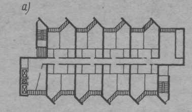
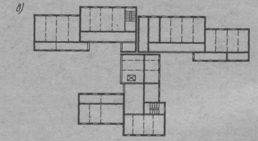
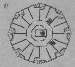
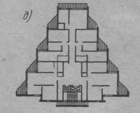
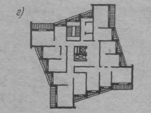
Fig. I.1. Frameless wall construction systems of residential buildings:
a, b - cross-wall (with parallel and radial bearing walls); c - longitudinal-walled; d, d - cross-wall
Using monolithic concrete it is possible to realize practically any architectural idea. Monolithic concrete is the most "convenient" material for creating unique structures, large public buildings with complex functions and, accordingly, a complex, multifaceted structure. The flexibility of monolithic concrete in housing construction is primarily manifested in the possibility of free choice of planning solutions for buildings.
Without significant complication of the technology of erection, residential buildings of various types can be built: conventional apartment, hotel, sleeping buildings of boarding houses, etc. It is easy to change the height of the floor in a monolith, which is very important for placing non-residential premises and offices in the ground floors. In such premises, the size of the spans and the height can be taken in accordance with the functional requirements of the embedded enterprises.
Depending on the size of the span of slabs, wall structural systems are divided into small-span (up to 4,8 m), medium-span (up to 7,2 m) and large-span (more than 7,2 m). In the practice of housing construction, small-span and medium-span structural systems are used.
In buildings with transverse bearing walls, horizontal loads acting perpendicular to the bearing walls are perceived by separate stiffeners located in the longitudinal direction of the building, a flat frame due to rigid connection of the transverse walls and floor slabs, radial transverse walls with the complex shape of the building in plan.
In buildings with longitudinal bearing walls, horizontal loads acting perpendicular to these walls are perceived by separate transverse walls of staircases, end walls and intersection walls.
In buildings with cross-bearing walls, horizontal loads, depending on the direction of their action, are perceived by longitudinal or transverse walls, and therefore this constructive system makes it possible to erect the most durable, rigid and stable buildings. In terms of height and in terms of the building, the constructive system can be regular and irregular. Regular systems include buildings with the same floor layout of walls and openings, and irregular buildings with vertical and horizontal structures of different sizes and types (for example, on the first floors of the column, and on the overlying ones floors - walls; the building has an expansion or narrowing of the wall dimensions in height, different heights, etc.) The choice of the structural system of the building in terms of strength and rigidity is based on static calculations and depends on the number of storeys, geological and soil conditions of construction.
The structural and technological type of the building is associated with the method of its erection. It is possible to distinguish two main and most common constructive-technological types of frameless buildings, erected in removable (adjustable) formwork.
Buildings of the first constructive-technological type.In buildings of this type, in the first stage, internal and external load-bearing walls are floor-by-floor, and at the second stage, overlaps are arranged. The inner walls of such buildings are always monolithic single-layer, external - monolithic and prefabricated monolithic. For the erection of walls in this case, large-scale or block formwork is used. (Fig.1.2.) 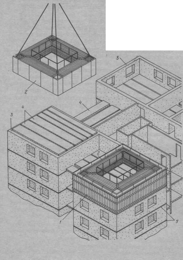
Fig. 1.2. Erection of the building of the first constructive-technological type in block and large-panel formwork: -
1- large-scale formwork;
2- block formwork;
3-monolithic wall;
4 - prefabricated slabs;
5-horizontal technological seam
Overlapping, used in buildings of the first constructive-technological type, as a rule, assembled from solid or multi-hollow slabs. It is possible to use prefabricated-monolithic and monolithic ceilings.
Buildings of the second constructive-technological type.In the buildings of the second type, at the first stage, simultaneously, either the bearing walls and ceilings of monolithic concrete are simultaneously erected. The outer walls are erected at the second stage.
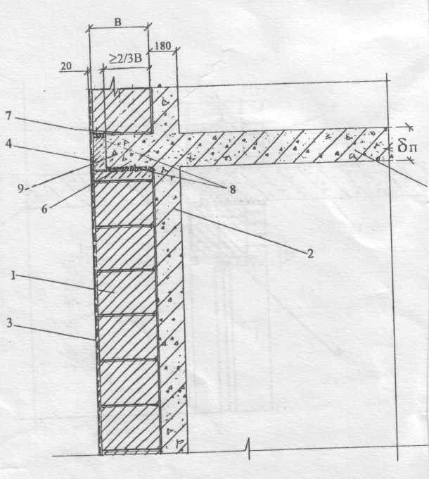
With the simultaneous erection of walls and ceilings, a volume-overlapping (tunnel) formwork is used (Fig.1.3.) 

![]()
Fig. 1.3. Construction of a second structural-technological type building in a bulk-shuttering (tunnel) formwork: 1 - L-shaped element of a bulk-shuttering formwork (semi-tunnel); 2 - traverse for lifting formwork; 3-shell formwork, installed on cross-shaped inserts; 4 - cross-shaped insert; 5 - face formwork of overlapping; 6 - end wall formwork; 7 - a blowing agent; 8 - fixing bolts of formwork; 9 - large-panel wall formwork for the device of the house end; 10-11 - working platforms; 12 - telescopic stand; 13-infrared radiator; 14-fence; 15 - tarpaulin for closing the tunnel during warm-up of concrete; 16-double
Internal walls are designed with single-layer monolithic ones mainly from heavy concrete. Concrete grade for compressive strength is assigned from the condition of ensuring the strength of the walls not lower than B15. The thickness of the walls is taken as a result of calculation for the force effects and must meet the requirements of sound insulation. The minimum thickness of inter-apartment walls is 160mm.
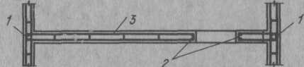


Fig.1. 4. Schemes of reinforcement of monolithic walls in buildings erected:
A) - in the usual engineering-geological conditions; b) in seismic regions. I - spatial frameworks, installed at the intersection of walls; 2 - frameworks installed at the edges of the openings; 3 - armoblok from flat skeletons; 4 - a spatial skeleton of crosspieces
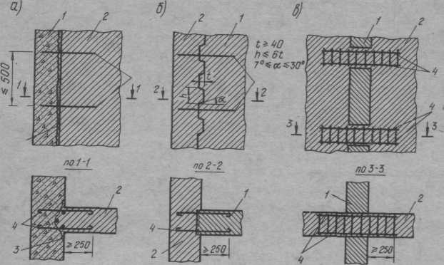
Fig. 1.5. Schemes of vertical butt joints of monolithic walls:
a - the keyless; b - with evenly distributed height dowels; c - with discretely arranged through keys: 1 - monolithic walls, concreted first; 2 - walls, concreted in the second turn; 3 - the cut-off from a woven grid, strengthened on a skeleton; 4 - horizontal reinforcement links
External walls can be made of single-layer monolithic of cellular concrete with a density of up to 900kg / m3 with the mandatory installation of an outer protective layer. The greatest application was found on the outer walls of the three-layer prefabricated structure, which meet the requirements of SNiP 23-02-2003 (Thermal protection of buildings).
Examples of enclosing structures:

Fig.1.6. Three-layered enclosing structure. 1). Consisting of cellular concrete (thickness -0.4 m), heat insulating material (polystyrene foam -0.1 m thick) and facing brickwork (thickness -0,125 m) 2). Three-layered enclosing structure. Composed of internal brickwork (thickness of -0.25 m), heat-insulating material (mineral wool board -0.1 m thick) and facing brickwork (thickness -0,125 m).
Overlaps are monolithic, prefabricated-monolithic and prefabricated.
 M
M
Fig. 1.7. Three-layered enclosing structure. Consisting of a monolithic reinforced concrete (thickness-0.18 m), a thermal insulation material (polystyrene concrete blocks of a thickness of 0.3 m) and plaster (thickness of 0.02 m)
1-polystyrene blocks,
2-monolithic reinforced concrete,
3-shotcrete-concrete (plaster).
oolitic ceilings are calculated and constructed as plates supported along the contour or on three sides with a fourth free side for a unified load for living quarters.
The prefabricated-monolithic ceilings represent a two-layer structure along the thickness of the slab: the lower layer is a prefabricated slab (shell) 40-60mm thick, used as a non-removable formwork; the top layer is monolithic concrete with a thickness of 120-140 mm. Calculation of prefabricated-monolithic flooring on a unified load for living quarters is carried out both for a solid monolithic slab. The prefabricated slab is manufactured using steel form-formwork in polygonal conditions from heavy concrete of class B15. The monolithic layer is made of heavy or light concrete of class not lower than B12.5.
Prefabricated slabs are used: solid for the size of the planning cell and multi-floor decking.
Lift shafts are made monolithic.
Stairs are made of unified prefabricated reinforced concrete marches and platforms, as well as in monolithic execution with the use of a special form-formwork.
2. CONCRETE. CLASSIFICATION AND COMPOSITION
2.1. Classification and composition
Concretes are classified according to a number of characteristics. (GOST 25192-82) By designation, constructive concrete is distinguished, from which the bearing and enclosing structures are manufactured. In terms of density, the concrete is divided into especially heavy (more than 2500 kg / m 3), heavy (1800 ... 2500 kg / m 3), light (500 ... 1800 kg / m 3), especially light (less than 500 kg / m 3 ).
According to the type of binder, concrete is distinguished: cement, silicate, gypsum, slag-alkali, etc. By the form of aggregates, concretes can be on dense, porous, and special aggregates.
According to the structure, concretes come with a dense, porous, cellular and coarse-porous structure.
The largest application in the practice of construction for the erection of monolithic structures of buildings have received structural heavy and light cement concretes, in the selected composition of which, usually include cement, water, aggregates and additives.
Cement - the main type of binder for the production of concrete mixtures. (GOST 30515-97)
Cement is classified according to the following characteristics:
Kind of clinker and material composition;
Hardening strength;
Hardening speeds;
Terms of grasp;
By the type of clinker, cement based on portland cement and alumina clinker is distinguished.
Cements based on Portland cement clinker on the material composition and depending on the content of active mineral additives are subdivided as follows:
Without active mineral additives - Portland cement;
With active mineral additives not more than 20% - portland cement with mineral additives;
With additives of granular slag, more than 20% - slag Portland cement;
With active mineral additives over 20% - pozzolanic portland cement.
According to the hardness of hardening, the following cements are distinguished:
High-strength - grades 550,600 and above;
Increased strength - grade 500;
Ordinary - 300 and 400 grades;
Low-quality - below grade 300.
The speed of hardening distinguishes cements:
Ordinary with a strength rating at the age of 28 days;
Fast hardening with strength rating at the age of 3 and 28 days;
Especially fast hardening with strength rating at the age of 1 day or less;
According to the terms of setting, the cements are classified into:
Slow-seizing, with the beginning of setting more than 1 hour 30 minutes;
Normally seizing, with the beginning of setting from 45 min. up to 1 hour 30 minutes;
Quick-seizing, with the beginning of setting less than 45 min.
Over time, cement activity decreases (30-40% per year), therefore it is necessary to strictly follow the rules and terms of its transportation and storage.
Fillers occupy up to 80% of the volume in concrete and significantly affect its strength, durability and cost.
As a small aggregate, sands are used for construction works (GOST 8736-93).
To produce high-quality concrete, sand must consist of grains of different sizes (a mixture of medium and coarse sand M cr = 2-3), so that the volume of voids in it is minimal, the smaller the volume of voids in the sand, the less cement is required to produce dense concrete. Use sand with a grain size of less than 1.5 and more than 3.5 is not recommended
A large aggregate in heavy concretes is gravel and crushed stone from dense rocks for construction works (GOST 8267-93).
For the production of lightweight concrete, large porous aggregates are used, ranging from 5 to 40 mm, including claydite and its varieties (shungisite, fly ash, clay-ash clay, expanded mudstone), thermolite, agloporite, slag pumice, granulated slag, expanded perlite and expanded vermiculite, as well as aggregates from porous rocks and industrial wastes (GOST 25820-2000).
For the preparation of concrete mix and watering of concrete in the hardening process, use any water from household water pipes, rivers or natural water bodies (GOST 23732-79).
One of the promising directions of reducing cement consumption, regulating the technological properties of a concrete mixture and the physical and mechanical characteristics of concrete is the application chemical additives in the production of concrete (GOST 24211-91).
The main effect of the action of the additives is divided into the following groups:
Regulators of rheological properties of concrete mixtures (plasticizing, stabilizing, water-retaining);
Regulators of setting and hardening processes (retarders of setting, hardening retarders, setting accelerators, hardening accelerators, antifreeze);
Regulators of the structure of concrete (air-entraining, foam-forming, gas-forming);
Additives giving concrete special properties (reducing wetting, changing the electrical conductivity);
Additives of multifunctional action (complex);
Additives that slow corrosion of reinforcing steel (inhibitors).
Some of the additives used at different dosages can have opposite effects (accelerate or slow down the hardening of concrete, cause corrosion of the reinforcement), therefore, the type and concentration of additives is prescribed using standard literature, installed in a construction laboratory in an experimental way.
Along with the use of chemical additives for the dilution of high-grade cements in the preparation of low-grade concrete in a concrete mixture, mineral additives:diatomite, ground granulated slag, fly ash, thermal power plant, etc. This makes it possible to increase the efficiency of concrete mixtures, especially in monolithic housing construction, where, for design reasons, high strength concrete is not required.
2.2. Selection of the composition of concrete
The composition of concrete is the mass or volume ratio of binder, aggregates and water (GOST 27006-86).
Most often, the composition of concrete is expressed in the form of a ratio: N: N, which shows how many times the amount of fine aggregate P (sand) and coarse aggregate R (crushed stone) is larger than cement (C). The consumption of cement in proportion is taken as one. It is necessary to indicate the water flow, which is expressed by the water / cement ratio W / C. For example, concrete with a composition of 1: 2.5: 4 at B / C = 0.5 corresponds to a consumption per unit of cement mass of 2.5 units of sand and 4 pieces of crushed stone.
Express the composition of concrete in the form of mass consumption of materials (kg), necessary for the preparation of 1 m 3 (1000 l) of concrete mixture. For example: cement - 300 kg, sand - 700 kg, crushed stone - 1200 kg, water - 150 kg. Only 2350 kg.
The composition of concrete is selected by special laboratories on the basis of information about the binder and fillers (cement activity, the highest strength of aggregates, the sand size module) in such a way that, with a minimum consumption of cement, obtain concrete with specified properties (specified hardening times, required concrete class, frost resistance grades and water resistance, necessary mobility or rigidity).
The composition of concrete is selected in a certain sequence:
Determine the value of water-cement ratio (according to graphs and tables) and the consumption of cement (C) and water (B) per 1 m 3;
Find the optimum ratio of sand, gravel, or gravel;
Set the grain composition of aggregates;
Determine the preliminary composition of concrete;
Trial batch test the mobility and workability of the concrete mix (if necessary, amend the calculation of the composition of concrete);
Finalize the consumption of materials per 1 m 3 of concrete mix;
Prepare test batches of control samples and test these samples to determine the strength of the concrete;
If the strength corresponds to a given class of concrete, the composition is approved for production.
When choosing a composition, the natural moisture content of the materials is taken into account.
2.3. Properties of concrete mixtures and concretes
The main technological property of the concrete mix is workability. It is estimated by the mobility indices (sediment of the cone OK) and stiffness (F) in accordance with test methods (GOST 10181-2000).
The classification of concrete mixtures according to the degree of their workability is given in Table. 2.1.
The mobility of the concrete mix depends on the content of water in it, the water-cement ratio, as well as the type of cement, the size of the aggregates, the amount and granulometric composition of the sand, the introduction of additives into the concrete.
Although increasing the water content in concrete, increasing mobility and improving workability, facilitates laying, excess water in concrete is harmful. It increases the probability of delamination of concrete mix, requires increased cement consumption, increases porosity and shrinkage of concrete, which reduces its quality. Therefore, in recent years, the increase in mobility of concrete mixes is achieved not by increasing the water content in them, but by the introduction of special chemical additives, plasticizers and superplasticizers (see section 3 of this manual).
Fig.4.1. Technological schemes of work on the construction of a monolith reinforced concrete foundation plate
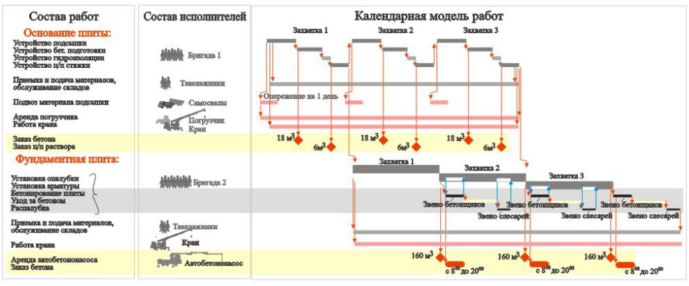
Fig. 4.2. A calendar model of works on the construction of a monolithic reinforced concrete foundation with a subdivision into three seizures and the use of two complex teams of workers
2.3.3. Technology and organization of work in the construction of monolithic structures of a standard floor
The most difficult element of the design work in the composition of such sections is the definition of the scheme of grabbing concreting on the standard floor. Such a scheme is formed as a set of ideas about the formwork used, the methods of supplying concrete, the organizational forms of work of the performers and the set deadlines.
In practical work the decisive role is played by the type and quantity of the formwork used. In educational design is characterized by the predominant use of large-paneled formwork of walls for crane installation and small-sectional formwork of floors for manual assembly and disassembly - this allows to include a wide range of shuttering systems of foreign and domestic production and to unify explanations. As a rule, in educational design there are no restrictions on the number of formwork and for a single-section house the kit must provide the installation of formwork to the entire floor or to the floor within one section (vertical and horizontal structures) with 10, ... 15% margin. For a multisectional house, the amount of formwork must ensure simultaneous operation of each concrete batching complex ("brigade + crane" or "brigade + crane + concrete pump + distributing boom") on two seizures (minimum) and more.
Along with the amount of formwork, the overall organizational and technological structure of concrete works on the standard floor of the building is simultaneously set in relation to the pace and volume of the concrete mix. There are many reasons for this:
- the given term of erection of a floor;
- direct dependence of the rate of turnover of the formwork and the pace of construction of the building on the rate of concreting;
- close interconnection of work on laying a concrete mixture with the work of the manufacturer of the commodity mix, transport organizations.
Working cycles of concrete laying with compressed work periods are often the central moments of the organizational and technological model of the construction of a standard floor of the building - it is to them that the remaining work is adjusted. The laying of concrete is usually assigned to fixed periods of working time: one working day or shift, less often half a shift. Sometimes the stacking of concrete can be arranged in shifts, by the days of the week, leaving Saturday and Sunday for keeping the structures. In real planning, everything will depend on the volume and the required pace of building, the possibilities and motivations of the construction organization, the regional features of manufacturing and supply of commercial concrete mix. For educational work, it is possible to recommend changing volumes of concrete laying per individual complex:
30-40m 3 when concreting walls and columns of small sections using the "cranbadia" method;
50-60m 3 for concreting ceilings and massive structures using the "crane-bucket" method;
60-100m3 when concreting ceilings and massive structures using a concrete pump and a distributing boom.
In accordance with these volumes and terms of work on the typical floor, the number and size of the seizure are selected, the number of formwork is specified, the required number of concrete-packing complexes is installed. In addition, the following organizational and technological features of concrete works are taken into account:
- in single-section buildings sometimes separate into a separate hitch a ladder-elevator block, - the installation of formwork and reinforcement in such blocks is more difficult and is slower than in ordinary floor structures. In general, the presence of a third clamp in the structure of the floor is highly desirable at a compressed rate of erection, when there is little time to maintain vertical structures in the formwork;
- in the presence of one tap and the use of the method "Crane-bucket" there are situations where when laying concrete it is impossible to perform active work on the installation and dismantling of the formwork and the bulk of the performers must have a front for manual work without the participation of a crane;
- the characteristic composition of manual works without the participation of a crane includes the binding of the reinforcement, the installation of the forming agents, installation and dismantling of the formwork of floors, cleaning, lubrication and minor repair of the formwork. In winter, these jobs are supplemented by the installation of heating wires or electrodes on the reinforcing cages, the installation of multiple switching connections, the insulation of the formwork and the external surfaces of the structures, the temperature control and the electrical maintenance of the holding. These works are carried out simultaneously with the main works, mainly in the part of combining the installation and switching of heating devices with reinforcement work.
- in the production of concrete works on a typical floor, a complex team of concrete workers is traditionally used, in which, in the right proportions, there are qualified locksmiths for assembly-disassembly of formwork, reinforcement, concrete workers. Usually in one shift in the brigade it's enough to have a link of locksmiths (2-3 people) for direct work with the crane when assembling and dismantling the formwork and the link of concrete workers (4-6 people). Almost always in the brigade should be present carpenters (1-2 people) for small repair work and devices of non-standard formwork. If necessary, all listed workers are easily retrained for armourers (manual toe-up and feeding reinforcing bars, other auxiliary work, knitting of simple grids under the guidance of an experienced link).
- the reinforcement workers make up the bulk of the concrete workers' brigade on the working horizon (10-15 people per shift and more). In addition, in the replaceable brigade there is a link of riggers (3-4 people), serving the acceptance, storage and supply of materials and, occasionally, the link of reinforcement workers, connected with the preparation of reinforcement products in the construction conditions. In the models given, such links are constantly
work at the bottom, at the ground level, and their numerical strength is selected depending on the labor intensity of the auxiliary and preparatory work for the total period of erection of the floor.
- to perform work on heating concrete in winter, it is advisable to provide a special link of workers, the number of which is determined by the laboriousness of the installation of heating wires in such a way that there is no delay in the reinforcement work. For 24-hour monitoring and maintenance of concrete, an additional link should be provided 2 people per shift: electrician and care worker
concrete and temperature control of aging.
Despite the variety of shapes and configurations of erected buildings, the organizational and technological structure of works using universal panel shuttering systems for floor erection of the above-ground part of buildings of 12-25 floors high has two basic types of solutions. For example, in Fig. 4.3 provides a conditional organizational and technological model of work for two seizures on a typical floor using a single crane and the method of supplying a concrete mixture to the formwork "crane-bucket". Here the main problem is the inability to install the formwork of the walls during the laying of concrete due to the use of the crane. Partly this problem is solved by transferring the bulk of the performers to manual disassembly of the formwork of the floors, as shown in the calendar model when performing work on the second floor, and / or by using the pre-knit frame of the walls before the formwork is installed.
The presence of a second crane or the use of a concrete pump and a dispensing boom completely removes this problem. However, traditionally, the terms for maintaining vertical structures in the formwork are traditionally shortened, which makes it advisable to organize work on the floor in three or four seizures to create any significant time for maintaining the walls and columns (the model in Figure 4.4).
When incorporating technological maps for the construction of monolithic structures for the thermal processing of concrete, the terms of aging must take into account the time of active heating in the formwork and passive cooling in the formwork, shelters or in the open air. AT general view, for walls and columns, the duration of the active heating and cooling of the concrete in the formwork is taken according to the schedule of works until the formwork is removed. For overlappings, the length of the active heating and cooling period to safe temperature differences is determined by the moment of the beginning of the assembly of the reinforcement and formwork of the walls of the next floor on this floor. Usually, at that moment, the insulation is removed and the upper surfaces of the plate are opened until the formwork is removed from the lower surface. The picture of switching on the heating of concrete on concreting concreting together with the knowledge of the volumes of concrete, the specific heating capacities required by types of structures, the power of the transformers or calorifiers used, makes it possible to determine the total required power and the number of means for heating concrete.

Fig.4.3. Technological sequence and calendar model of concrete works on the standard floor of a monolithic residential building in two seizures at a rate of erection of a floor of 11 days and the use of one tap

Fig.4.4. Technological sequence and calendar model for the execution of concrete works on the standard floor of a monolithic residential building in three seizures at a rate of erection of a floor of 10 days and the use of a crane and a concrete pump
2.3.4. Technology and organization of work in the installation of outdoor and internal walls, partitions on the type floor
The technology of external multilayer walls provides a detailed description of the construction of the wall as the composition and thickness of the layers, the structure of the bonds of the layers. Here the stages of wall formation are specified. For walls made of small stones, this is most often the description of the order of the installation of tiers of masonry, for example: laying of a layer of the outer facing part of the wall in height of 4-5 rows; laying of the inner wall; installation of a tier of vapor barrier and insulation; the device of connections of the inner and outer walls. Typical schemes from workflow maps are used to describe these works.
- receptions and means of supplying materials to the floor (usually either using a crane at remote sites, or special lifts also to remote sites);
- ways of transportation of materials on a floor (more often - manually, on wheelbarrows);
- means podschivaniya (often with the help of mobile inventory scaffolding when working indoors and using hanging scaffolds or scaffolding when working from the side of the facade). Means of podschavaniya necessarily reflected in the composition of technological schemes for the production of work with the development of parts and components that explain the features of their installation and attachment;
- means for ensuring the safety of work (usually special fencing of the marginal areas of work);
- (usually decided by the appointment of a team of bricklayers for the masonry and brigade itself or a link of handymen to ensure the supply of materials to the floors and work areas).
In the same way, descriptions of technology and organization of work are constructed for the construction of internal walls and partitions. Organizationally, the installation of external self-supporting walls and internal partitions and walls of small pieces of stones, usually provides a team of bricklayers. The brigade's work on installing windows and doors is attached to the work of this brigade, usually with a delay of 1-2 floors at the same pace of work on the standard floor.
2.4. Development of the section "Used machines, equipment and adaptations"
This section includes the parametric selection of the main construction machines (crane, concrete distributing boom, etc.) and compilation of the form sheets for the formwork, basic equipment and devices.
The required amount of formwork is determined by the specification during the drawing up of formwork drawings taking into account the number of seizures and concrete batching kits (Form 7)
The main technical means for supplying and laying concrete mixes are:
Mounting crane;
- bunkers / tubs / rotary and non-rotating;
- load-lifting devices for lifting reinforcement, bunkers;
- a tool for laying and compacting a concrete mixture.
- concrete pump plants (stationary or self-propelled);
- concrete distributing installations (arrows);
- inventory scaffolding and scaffolding (usually included in the shuttering system used and specified in the formwork specification)
The main technical means for assembling prefabricated structures and large formwork elements, supplying materials, etc. are:
Mounting crane;
- load-gripping devices;
- devices for reconciling and temporary fixing of mounted elements;
- devices that ensure safety at altitude. The main technical means and devices for providing
the works on the installation of external and internal walls and partitions are:
Mounting crane;
- cargo and cargo-and-passenger lifts;
- remote sites for receiving materials from the crane and lift;
- facade platforms;
Rack forests;
- hinged forests and scaffolding;
- mobile light scaffold for the construction of internal walls;
- inventory fencing of edge zones, protective canopies of various types
- means for manual transportation of materials and structures;
- the solution boxes for acceptance of ready-made mixtures;
- lightweight concrete and mortar mixer, water tanks for the preparation of mortar in place.
2.4.1. Selection of load gripping devices
The choice of lifting devices (slings, traverses) is made for each of the prefabricated elements of the building, as well as for lifting shuttering bulk blocks and panels, reinforcement nets, frames and bunkers with concrete mix. At the same time, each of the selected load handling devices should be as versatile as possible so that the total number of devices on the construction site is the least.
When constructing multi-storey buildings, universal cable ropes are widely used, equipped with chalk hooks for lifting prefabricated elements, formwork blocks and panels for mounting loops (according to GOST 25573-82). The standard provides the following types of rope slings: 1KK - single-branch; 2SK - two-branch; 3SK - three-branch; 4SK - four-branch (execution 1 and 2), UPC - two-loop (execution 1 and 2); CCMs are circular (versions 1 and 2). To mount the elements of the tunnel formwork, special traverses "Duck's nose" are used.
Along with unified general purpose lines, special slings are used, designed for a certain range of products and slinging schemes. To lift slabs with six suspension points, balancing slings with blocks providing uniform tension of the slings' branches are used.
Traverses are used to lift long structures, when the use of conventional lines is impossible.
In general, the selection of slings and traverse is made by calculation. When lifting commercially produced construction products and structures, it is possible to use unified load-gripping devices (within their passport carrying capacity) and conduct work on standard slinging schemes for elements. The data on the accepted load-gripping devices is entered in the form 8.
The list of requirements for load-handling devices and | |||||||
mounting rigging | |||||||
Load- | Needed | Appointment |
|||||
device, | slinging, | ||||||
Lecture 11
TYPES OF CIVILIAN BUILDINGS
Monolithic is called building structures, mainly concrete and reinforced concrete, the main parts of which are made as a single whole (monolith) directly on the site of the erection of a building or structure. When combining monolithic structures with prefabricated structures, the method of erection and the final construction are called prefabricated-monolithic. The method of erecting buildings from monolithic and precast-monolithic reinforced concrete allows one to obtain various forms of buildings, any shapes and sizes of openings, different storeys, etc. However, the requirements for the unification of geometric parameters, loads, types of products should be observed in the same way as for full-sized buildings.
Entirely monolithic buildings - residential, public, industrial - are erected with both bearing walls and with the use of a frame, depending on technological and functional requirements. The distinctive features of such solutions are the clarity and simplicity of the structural forms: columns - round or rectangular section; overlapping - mostly bezbalkovye, providing freedom in the arrangement of partitions, i.e. freedom of planning decisions; Vertical diaphragms of rigidity simplify the design of knots of overlapping of columns with columns, working in this case only on vertical loads; all floors of pipes for electric and low-current devices are laid in the ceilings, which eliminates the need for the installation of suspended ceilings or underfills under the floors in which pipes are usually placed.
The use of spatial hardness cores made of monolithic reinforced concrete for multi-storey frame buildings allows to build these buildings with complicated configuration in terms of, with a variety of space-planning solutions. In the constructive aspect, the formation of a solid, box-like in the plan section of the core of stiffness instead of flat walls of rigidity but many times increases the spatial rigidity of the building, and also significantly reduces the consumption of concrete and steel.
One of the effective directions in the construction of multi-storey buildings is the use of prefabricated monolithic large-panel elements. However, the erection of buildings from standard panels is limited to a height of 20-25 floors. With this number of storeys in the panels there are significant efforts from wind loads, which lead to the exhaustion of their load-bearing capacity. Increasing the number of storeys can be achieved by combining a panel system with a monolithic hardness core that senses all horizontal loads acting on the building, freeing the panels to work only on vertical loads.
Monolithic and prefabricated monolithic systems used in housing construction are oriented mainly to frameless structural systems in a cross-wall or cross-wall version. With mixed structural systems, the first floor is a skeleton, the upper floors are frameless.
Monolithic building construction obeys the stringent requirements of unification: a step of longitudinal and transverse walls of 2.7-7.2 m with a gradation of 300 mm; height of residential floors 2,8 and 3 m; height of non-residential floors 3,3; 3.6; 4,2 m; step of load-bearing structures of the first non-residential floors: 6.0; 6.6; 7.2 m - can be adopted regardless of the pitch of the load-bearing structures of the upper floors of the building.
Unification made it possible to provide for a number of options for solving basic building structures, depending on the production and material capabilities of the construction area. Constant in all versions are monolithic inner walls with a thickness of at least 160 mm when made of heavy concrete and at least 180 mm - from a structural lung.
On the basis of technology, a variety of monolithic and prefabricated monolithic walls can be reduced to three modifications: the walls are completely monolithic; Walls containing only a monolithic layer (or belt); Walls that do not contain monolithic concrete inclusions.
The first group of wall structures is solved when building buildings in large-panel and block formwork. Monolithic walls project with single-layer lightweight concrete of density 1000-1200 kg / m, class not lower than B3.5. It should be noted that modern energy-economic requirements have limited the scope of such designs to the southern regions of the country.
Prefabricated-monolithic walls contain prefabricated elements. Monolithic layer thickness not less than 120 mm from heavy or light dense concrete. The prefabricated wall element - the "shell" - has warming and protective-finishing functions, is located outside the monolithic layer, being its leaving formwork. The "shell" team may have several design options: a single-layer lightweight concrete panel; panel of structural lightweight concrete with insulation liners; reinforced concrete ribbed panel with a thickness of a plate of 80 mm and an effective insulation. "Shells" are attached to a monolithic layer by flexible connections.
When the climatic conditions allow to apply insulation from the inside, the thickness of the monolithic layer is not less than 160 mm when it is made of heavy concrete and at least 200 mm - from lightweight concrete. The inner insulation layer is made of aerated concrete blocks with a density of 300-350 kg / m.
The rational area of use of monolithic reinforced concrete is the construction of overlapping for large loads, in particular, the device bezobalochnyh overlap. The erection of such overlaps by the method of lifting is one of the progressive methods. The main features of the method of lifting the floors are to produce a "package" of floors in the form of flat monolithic reinforced concrete slabs at the ground level and gradually raise them along the guide supports. The guiding supports are prefabricated reinforced concrete or metal columns, as well as monolithic reinforced concrete hardness cores, built in a sliding or sliding formwork. Overlapping is raised using special jacks, mounted on columns.
Advantages of this method are: the ability to create a variety of space-planning solutions of buildings both by changing the configuration of the side formwork of the floors, and due to the lack of protrusions from the ceilings of beams and crossbars, arbitrary arrangement in terms of columns; complex mechanization of building processes, ease of doing a significant part of the work at the ground level; Possibility to build facilities in conditions of a limited construction site (due to the absence of land cranes and minimum areas for storing materials), which is particularly important in conditions of construction on a complex terrain or on crowded sites among the existing urban development.
The prefabricated-monolithic ceilings consist of two elements: a lower collection plate with a thickness of 40-60 mm and a monolithic upper concrete layer 100-120 mm thick.
Prefabricated ceilings are assembled from typical products used in mass construction: slabs of solid cross-section or hollow-core elements.
Stairs, partitions, lift shafts of monolithic and prefabricated-monolith buildings are made of prefabricated.
Theme 4.2. Large-panel buildings
Large-panel buildings are called, assembled from pre-fabricated large-sized planar elements of walls, ceilings, coatings and other structures. Prefabricated structures have increased factory availability - finished exterior and interior surfaces, built-in windows and doors.
According to the constructive scheme of the building there are: frameless, with longitudinal and transverse bearing walls and frame.
Frameless buildingsconsist of a smaller number of prefabricated elements, are easy to install and have a primary use in mass housing construction. In these buildings, the external and internal walls perceive all the acting loads. Spatial stiffness and stability are provided by the mutual connection between the panels of walls and ceilings. There are four constructive options Support of slabs: on longitudinal bearing walls; on the contour; on the internal transverse walls; on three sides (on the longitudinal carrier and internal transverse).
AT wireframepanel buildings, the loads acting on them perceive the crossbars and racks of the frame, and the panels perform most often only protective functions. Distinguish the following design schemes: with a full transverse frame; with a full longitudinal frame; with a spatial framework; with an incomplete transverse frame and bearing outer walls; with the description of overlapping plates at four corners directly on the columns; with support of plates on external panels and on two racks on an internal line. These schemes are especially effective for public buildings.
An important stage in the design of large-panel buildings is the selection of the wall cutting system (Figure 4.1).
In large-panel buildings use horizontal layout(single-row cutting) division - is formed by single-storey panels the size of one room (with one window), two rooms and a strip (of striped belt and panel panels). Vertical scheme(two-row cut) is formed from the panels on two floors: with one window on the floor and a strip of two-storey pro-
Fig. 4.1. Schemes for cutting the facade of a building on a panel: a - on a room with a window; b - two rooms with windows or window
and a balcony door; в - a tape hinged panel; d - wall panels on two floors with window inserts
wall panels and inter-floor belt panels. In civil engineering, the horizontal layout of the walls was most widely used.
Wall panel constructions
To the wall panels, in addition to the basic requirements imposed on the exterior walls (strength, low thermal conductivity, low mass, fire resistance, economy), special requirements are imposed: manufacturability of manufacturing in the factory; simplicity of installation; perfect joint design; high degree of factory readiness.
Wall panels due to their considerable length and height with a small thickness are not resistant. This stability is provided by fastening the panels together, with overlapping structures, etc. Depending on the type of the constructive scheme wall panels are divided into carriers, self-supporting, hinged. Panels of external walls can be single- and multi-layered.
Single-layer panelsare made of a homogeneous low-heat-conducting material (light or cellular concrete), the strength class of which must correspond to the perceived loads, and the thickness - to take into account the climatic conditions of the construction area. The panel is reinforced with a welded frame and mesh. On the outside of the panel there is a protective layer of heavy concrete with a thickness of 20-30 mm and on the inside - a finishing layer of cement or lime-cement mortar 10-15 mm thick. A good material for single-layer panels is cellular concrete with a density of 600-700 kg / m. The thickness of the panels depends on the climatic conditions and is assumed to be 240-320 mm. These panels are used for buildings with internal transverse bearing walls, where the outer wall panels are self-supporting.
Double layer panelsconsist of a carrier layer of dense light (density\u003e 1000 kg / m 3) or heavy concrete class B10-B15 ^ and a thermal insulation layer of lightweight or cellular concrete or rigid insulating boards. The thickness of the carrier layer for wall panels should be at least 60 mm, it is located on the inside of the room, so that it is also a vapor barrier. Thermal insulation layer outside protect with a layer of decorative concrete or mortar grade 50-70 with a thickness of 15-20 mm.
Three-layer panelsconsist of two reinforced concrete slabs and an effective thermal insulation layer (insulation), laid between them. As a heater, semi-rigid mineral wool boards, expanded polystyrene, fiberglass mats, as well as rigid insulation - foam glass, foam silicate, foam concrete, etc. are used. The reinforced concrete layers of the panel are joined together by welded reinforcing bars. The inner layer of the three-layer panel is 80 mm thick and the outer layer 50 mm thick. The thickness of the insulation layer is determined by heat engineering calculation.
Asbestos-cement slabscan have a skeleton and frameless structure. The frame panel consists of two asbestos-cement sheets: the outer thickness of 10 mm, the inner - 8 mm and the frame between them from asbestos-cement bars of a special profile. Inside the panel, a heater is laid. Plates are attached to the frame on a strong polymer glue. Frameless panels consist of an outer asbestos-cement sheet 10 mm thick, which is given a box-like shape, and a second flat sheet forming the inner surface of the panel. A sheet of insulation is laid between sheets. The thickness of the panels is 140 mm.
Interior wall panelsare made of heavy or lightweight concrete (slag concrete, expanded clay concrete), as well as cellular and silicate concretes. According to the constructive solution, the bearing panels of the inner walls can be solid, hollow, often ribbed, with ribs along the contour. Their height corresponds to the size of the floor, and the length is a multiple of the dimensions of the structural cell of the building. Panels of transverse walls are made the size of a room, panels of longitudinal walls - for 1-2 rooms.
For frameless large-panel buildings, the following structural schemes are typical:
with a small step of bearing transverse walls- 2.7-3.6 m, transverse and longitudinal walls buildings - bearing. Panels of external walls are single-layer or three-layered, internal walls - reinforced concrete 120-160 mm thick. Plates of overlap - reinforced concrete solid 120 mm thick with support on the contour. The foundation of external self-supporting walls is prefabricated reinforced concrete blocks, internal bearing walls - reinforced concrete slabs of rectangular shape. The outer walls of the underground part of the building are erected from expanded clay concrete or reinforced concrete three-layer socle panels. The internal transverse walls are made of reinforced concrete panels 120-160 mm thick. Overlapping above the basement - from flat reinforced concrete slabs 120 mm thick, supported along the contour; with a large step of bearing transverse walls- 3.6-7.2 m, carrying transverse walls of flat reinforced concrete panels with a thickness of 160 mm. External longitudinal walls - self-supporting single-row or waist cuts from panels made of lightweight or cellular concrete. Interior partitions - gypsum concrete with a thickness of 80 mm. Overlap plates - solid reinforced concrete with a thickness of 160 mm or hollow-core thickness of 220 mm;
with a mixed pitch of bearing transverse walls.External walls - self-supporting single-row cuts from expanded clay panels. Plates overlap - solid 160 mm thick, supported in narrow cells along the contour, in wide cells - on two sides, or hollow-core thickness of 220 mm. Underground part buildings with a large and mixed pitch of bearing transverse walls: foundations of internal walls - reinforced concrete slabs laid with a continuous or intermittent tape; under the outer walls (sections between the tapes of the foundations) lay concrete preparation thickness of 100 mm. Internal walls of the underground part are assembled from reinforced concrete panels with a thickness of 160 mm with openings for passage and communication lines. External walls - from ribbed reinforced concrete socle panels, insulated with expanded clay concrete. The basement is covered with hollow-core slabs with a thickness of 220 mm or with a continuous thickness of 160 mm;
with three longitudinal bearing wallsspan 6 m. Outer longitudinal walls - bearing of expanded clay concrete panels up to 400 mm thick. The inner longitudinal wall is a carrier of flat reinforced concrete panels with a thickness of 160-200 mm. Overlap plates - reinforced concrete 160 mm thick. The underground part of the building is built of trapezoid foundation slabs, socle panels and panels of internal walls.
In buildings with transverse arrangement of load-bearing walls, the stairs consist of platforms and marches. Staircases are laid on the longitudinal walls and mounting tables of the transverse walls. Stair flights are supported by a quarter of the longitudinal edge of the platform, and the fittings are welded together.
In buildings with longitudinal arrangement of load-bearing walls, stairs are made of marches with half-surfaces supported on the longitudinal walls of the building.
The balconies are cantilevered in outer wall, they can be fixed with interfloor overlapping or additionally supported on an attached L-shaped stand. The slabs of the balcony have a take-out to 1.2 m. The floors are cement or ceramic tiles with a slope from the building. Fencing height of 1050 mm - in the form of a steel grating or protective screen of sheet materials.
Joints for externaland internal large-panel buildings
The conjugation of the wall panels between themselves and with the ceilings is called joints.The performance characteristics of large-panel houses largely depend on the design of joints. Joints must be strong, durable, water and airtight, have sufficient thermal protection and be simple in the way of embedding.
The joints of the outer walls are subdivided by their arrangement into horizontal and vertical ones.
Vertical joints by the way the panels are connected to each other are divided into resiliently and rigid (monolithic).
At the device resiliently coupled joint(Figure 4.2), the panels are connected by means of steel bonds welded to the embedded parts of the elements to be joined. In the groove formed by the quarters, enters the depth of 50 mm wall panel of the inner transverse wall. Connect the panels using a strip steel strip, with
Fig. 4.2. The design of the vertical elastically compliant joint of the panels:
1 - a steel overlay; 2 - embedded parts;
3 _ heavy concrete; 4 - thermowell; 5 - strip of waterproofing
or roofing felt; 6 - gernite or poroizol; 7 - solution or sealant
to the panel inserts. To seal the joint into its narrow slit, a sealing cord of hernite is put on the glue or porosol on the mastic. On the outside, the joint is smeared with a special mastic - thiocal sealant. For insulation from penetration of moisture from the inside of the joint, a vertical strip of one layer of waterproofing or roofing material is pasted on the bituminous mastic. Vertical joints are filled with heavy concrete. The disadvantage of resilient joints is the possibility of corrosion of steel bonds and embedded parts. Such fasteners are flexible and do not always ensure a long-term joint operation of the mating panels and, consequently, can not protect the joint from the appearance of cracks.
More common are rigid monolithic joints.The strength of the joint between the elements to be joined is ensured by embedment of the connecting steel reinforcement with concrete. In Fig. 4.3 shows a monolithic joint of single-walled wall panels with loop outlets of reinforcement, connecting brackets of round steel with a diameter of 12 mm. An air vertical cavity is formed between the interlocked joint zone and the sealant, which serves as a drainage channel diverting the water that enters the seam and discharging it out at the base level. Often, a mineral wool liner wrapped with polyethylene film or of foam is placed in the joint of panels to increase its heat-shielding properties.
Fig. 4.3. Monolithic vertical joint:
a - vertical joint; b - the same with a warming bag;
1 - external claydite-concrete panel; 2 - an anchor with a diameter of 12 mm;
3 - drainage channel; 4 - porosol bundle; 5 - sealant;
6 - a lining; 7 - staples; 8 - concrete; 9 - internal carrier panel
from reinforced concrete; 10 - a loop; 11 - mineral wool pack
For the construction of rigid joints, welded anchors are also used, which are T-shaped elements made of strip steel and located at the junction "on the edge". At the same time, in the wall panels, the end releases of the reinforcement (within the dimensions of the molds) are left, which are welded after the panels are installed to the ends of the anchors. Such a connection makes it possible to ensure a dense filling of the joint cavity with concrete, almost threefold lower the consumption of steel.
Vertical joints according to the peculiarities of sealing of the outer part are: closed,protected from the outside with cement mortar, sealing mastic, elastic gasket, and from the inside - with a layer of roofing material, a warming bag and monolithic concrete; openwith separate water and airtight barriers; The water-resistant tape, not allowing moisture inside the joint, simultaneously pulls it out; drainedoutside protected as well as closed joints, but their design allows a floor drainage of moisture, trapped inside the joint. The moisture flows down through the decompressor channel, and is drained out through the drainage hole at the intersection of the vertical and horizontal joints with a drainage apron. Thus, the drained joint by the method of sealing refers to the closed, and by the nature of the work - to the open.
For the device horizontal jointsthe top wall panel is laid on the bottom on the cement slurry. In this case, through a horizontal seam, densely filled with a solution, the rainwater can penetrate due to capillary suction of water through the solution. Therefore, at the junction they arrange a protivodozhdevoy barrier, going from top to bottom. On an inclined part, the solution is interrupted and an air gap is created, within which the moisture rise through the capillaries ceases (Figure 4.4).

FIG.4.4. The design of a horizontal joint of single-layer wall panels.
1 - reinforced concrete floor panel; 2 - cement mortar; 3 - wall panel; 4 - anti-rain barrier; 5 - sealing
mastic (thiocolol or polyisobutylene UMS-50); 6 - poroizol or gernite; 7 - thermowell in the waterproofing shell
Fig. 4.5. Types of joints of columns: a - spherical; b - flat nonmetallic; 1 - spherical concrete surface; 2 - outlets of reinforcing bars; 3 - connecting niches;
4 - groove for mounting the yoke; 5 - solution or fine-grained concrete;
6 _ centering concrete ledge; 7 - welding of valve outlets
The connection of the panels of the internal walls of frameless buildings is carried out by welding the connecting rods with a diameter of 12 mm to the embedding parts at the top of the panel. Vertical seams between the panels are filled with elastic gaskets made of antiseptic soft fibreboard, wrapped with roofing felt, and the vertical channel is filled with fine-grained concrete or mortar.
Frame-panel buildings
Frame-panel buildings are widely used in the construction of public buildings. They are characterized by two design schemes - with a transverse and longitudinal arrangement of crossbars.
Elements of prefabricated reinforced concrete frame include pillarsrectangular section with a height of one or two floors with one console for the outer row and two consoles for the middle row; crossbarst-section with one or two shelves for support of slabs and staircases; floor slabs(hollow or solid) consisting of intercolumny (bond), walled with grooves for columns and ordinary plates with a width of 1200, 1500 mm.
The conjugation of the frame elements carried out on the support is called a node. The site includes:
joint of columns:the column is supported through the concrete ledges of the heads, welding the outlets of the armature and fixing the joint (Figure 4.5); supporting the crossbar on the console of the column:on the surface of the console is fixed by welding embedded parts, on top of a steel plate welded to the embedded parts of the column and crossbar, then the seams are cemented with a solution (Figure 4.6); supporting the slab on the crossbar:the laid boards on the shelves of the crossbars are joined together by steel ties, the gaps between them are sealed with a solution. Distinguish the following frame systems: frame, frame-svyazevye, bond.
Frame system(Figure 4.7) consists of columns rigidly connected to them with crossbars, located in mutually perpendicular directions and forming a rigid structural system.
Frameless-bond systems(Figure 4.8), the joint work of the frame elements is achieved due to the redistribution of the share of participation in it frames and vertical walls-connections (diaphragms). Walls-diaphragms are located throughout the height of the building, rigidly fixed in the foundation and with adjacent columns. They are placed in the direction,
Fig. 4.6. The assembly of the crossbar with the column:
1 - column; 2 - the embedded part; 3 - connecting strip;
4 - deadbolt; 5 - cement mortar

Fig. 4.7. The scheme of the building with a frame system: 1 - column; 2 - crossbars

Fig. 4.8. Scheme of buildings with frame-bonded frames:
a - with flat connections; b)with spatial connections;
1 - columns; 2 - crossbars; 3 - flat bond elements
perpendicular to the direction of the frames, and in their plane. The distance between the wall-ties usually takes 24-30 m. These systems are used in the design of public buildings up to 12 floors with unified constructive-planning grids bhbbhZm.
For public buildings of large number of storeys apply link systemsskeletons with spatial bonded elements in the form of rigidly connected among themselves at an angle of walls or spatial elements that run along the entire height of the building, forming the so-called hardness core (Figure 4.9). These spatial bond stiffeners are fixed in the foundations and connected to floors that form floor-to-ceiling horizontal connections-diaphragms (disks), which perceive the horizontal (wind) loads transmitted to the walls. Spatial bond elements are usually located in the central part of high-rise buildings.
The spatial rigidity of frame-panel buildings is ensured by: rigid interface of the frame elements in the nodes; installation of walls of rigidity; laying bond and wall plates
Fig. 4.9. Scheme of buildings with bonded elements: a - box; b - X-shaped; at- round; g - I-rays
between the columns of the building; sealing joints between slabs; the device of communications of walls of staircases and elevator shafts by a frame of a building.
The walls of frame buildings are panels of light or cellular concrete with a thickness of 250-300 mm. By location in the wall, panels are distinguished: waist(socle, interstore, parapet) length of 3-6 m and a height of 0.9-2.1 m; prostennyewidth of 0.3-1.8 m and a height of 1.2-2.7 m; angularfor external and internal angles. Wall panels can be self-supporting and hinged. The panels rest on the floor or on the outer longitudinal bolt. To the column, wall panels are attached using steel elements welded to the embedded parts.
In Table. 4.1 shows the technical and economic indicators of panel buildings.