Classification of systems of grounding of electrical installations and modernization of apartment electric wiring. Experience of application.
To properly repair or upgrade the wiring, you need to know exactly which earthing system is applied to the facility. Your safety depends on this, in addition, it is important when drawing up a reconstruction project. In some cases, for example, a three-wire cable is used, and in others four and five-wire.
Classification earthing systems for electrical installationson IEC
The International Electrotechnical Commission and with its submission 7 edition of the PUE (rules for the installation of electrical installations) distinguish between 3 grounding systems and several of their subsystems.
1. System TN (subsystems TN-C, TN-S, TN-C-S);
2. The TT system;
3. The IT system.
TN System
The TN system, this dead-neutral system, at which the open conductive parts of the electrical installation are connected to the grounded source neutral with the help of zero protective conductors.
Term deadly grounded neutral means that at the transformer substation the neutral (zero) is connected directly to the ground loop (grounded).
The subsystem TN-C, is TN, in which the zero protective and zero working conductors are aligned along its entire length, i.e. .
TN-S is a system in which the zero protective and zero working conductors are separated all along. This is the safest, but also the most expensive system.
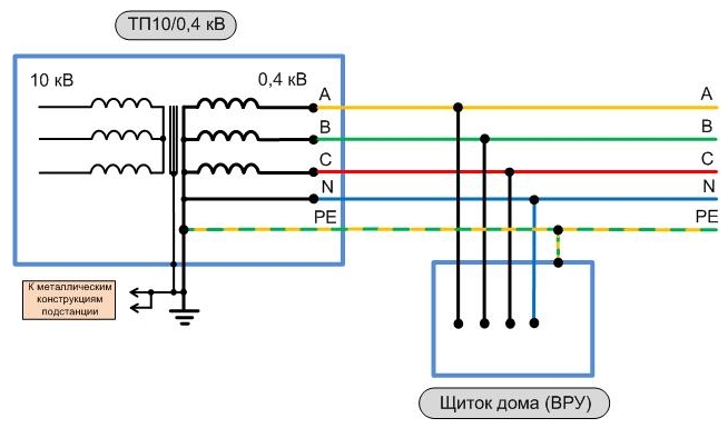
Subsystem TN-C-S is an intermediate option. In it the zero protective and zero working conductors are combined in some part of it. Usually this is the main shield of the building (protective grounding is supplemented by a protective zanuleniem). Further along the building these conductors are separated. This system is optimal from the point of view of the relationship between price and quality.
IT system
This is a system in which the source zero is isolated from the ground, or grounded through devices having a large resistance, and the open conductive parts of the electrical installation are grounded by means of grounding devices. Now the IT system is almost never used.
TT system
This is a system in which the source zero is grounded, and the open conductive parts of the electrical installation are grounded by means of a grounding device that is electrically independent from the source grounded. In other words, it uses its ground loop on the object in no way connected with zero.
Today, this system is the main one for mobile facilities, for example, cabins, house-cars, etc. Note that it is more difficult to coordinate the use of such a system than TN. It becomes mandatory, you need a good ground (4 ohms for 380 V), there are special features when selecting.
What kind of electrical installation system to use and how to modernize?
Based on the foregoing, it is best to use a TN grounding system.
The TN-C system was used earlier and it can not be recommended for new housing.
The TN-S system is all good, but the road is still rarely used. The optimal option so far is the TN-C-S system.
Let us now dwell on the typical difficulties and errors encountered in the modernization of grounding systems.
1. If we consider a private house in which the wiring is already made with a three-wire wire (phase, zero, ground), then replacing TN-C with TN-C-S is quite simple. You only need to make a good ground connection, connect it to the input electrical switchboard and connect the PE wires of the outlets and the light fixtures to the zero and ground connection point (N and PE) (usually this is a green-yellow wire).
2. In an apartment or apartment building, not equipped with a ground loop, this can not be done. Of course, it is better to make the wiring also with a three-wire cable, but it is not necessary to connect it, or in outlets (fixtures) not in.
The reason is that if you connect this wire to the zero wiring (there is nowhere else to connect it except except for the battery, which is forbidden), then due to the drop of the voltage in the zero wire from the currents of the included loads, the housings of your equipment will be energized relative to the ground batteries, pipes, etc.).
3. Other incidents are encountered during operation, for example, after elimination of the accident, electricians interchange the zero and phase conductors. Neighbors, who do not have a zero wire on the case of the equipment, do not threaten anything, and you have a case under the potential of the phase!
4. It is not uncommon for the input cable to zero in the zero, which occurs when the phase is skewed, in this case the housing will also have a dangerous potential.
Proceeding from the foregoing, the need arises. These are devices that turn off the 220/380 V network when little (but sensitive!) Currents flow through the human body 10-30 mA. The disadvantage of these devices is that they will work at any leakage currents, for example, when you are spilled by neighbors. It happens very difficult.
So, when repairing the wiring, use the TN-C-S grounding system. Route wiring with colored core insulation (for example, NGV NGG).
If the house does not have a ground loop, do not connect the ground wire to zero. For wiring in rooms where there is a lot of moisture, use.
Generally speaking, it can be seen that the great and terrible power of electricity has long been described, counted, entered in thick tables. The regulatory framework, which determines the path of sinusoidal electrical signals at a frequency of 50 Hz, can plunge any neophyte into horror by its volume. And, in spite of this, any habitue of technical forums has long been known - there is no more scandalous issue than grounding.
The mass of contradictory opinions in practice contributes little to the establishment of truth. Moreover, this issue is in fact serious, and it requires a closer look.
Basic concepts
- electrical connection of the object from the conductive material to the ground. Grounding consists of a grounding conductor (a conductive part or a plurality of connected conductive parts in electrical contact with the ground directly or through an intermediate conductive medium) and a ground conductor connecting the grounded device to the earth electrode. The earthing device can be a simple metal rod (most often steel, less often copper) or a complex set of elements of a special shape.
The quality of the ground is determined by the value of the electrical resistance of the grounding circuit, which can be reduced by increasing the contact area or conductivity of the medium-using multiple rods, increasing the salt content in the ground, etc. The grounding device in Russia, the requirements for grounding and its installation are regulated by the Rules for the installation of electrical installations (PUE).
Conductors of protective earthing in all electrical installations, as well as zero protective conductors in electrical installations with voltage up to 1 kV with deadly neutral, including bus bars, must have the letter designation PE and the color designation with alternating longitudinal or transverse strips of the same width (for tires from 15 to 100 mm ) of yellow and green colors.
Zero workers (neutral) conductors are denoted by the letter N and blue. Combined zero protective and neutral conductors must have the letter designation PEN and color designation: blue throughout the entire length and yellow-green stripes at the ends.
Types of grounding
The TN-C system (Fr. Terre-Neutre-Combine) was proposed by the German AEG concern (AEG, Allgemeine Elektricitats-Gesellschaft) in 1913. Working zero and PE-conductor (Protection Earth) in this system are combined into one wire. The biggest drawback was the formation of line voltage (1,732 times higher than the phase voltage) on the bodies of electrical installations in the event of an abrupt zero break.
Despite this, for today it is possible to meet this earthing system in the buildings of the countries of the former USSR.
To replace the conditionally dangerous TN-C system in the 1930s, the TN-S (Terre-Neutre-Separe) system was developed, the working and protective zero in which was divided directly into the substation, and the earth electrode was a rather complicated design of metal fittings.
Thus, if the working zero in the middle of the line breaks, the electrical installations do not receive a line voltage. Later, such a grounding system allowed the development of differential automata and leakage-triggered automata capable of sensing a negligible current. Their work to this day is based on the laws of Kirghof, according to which the current flowing through the phase conductor must be numerically equal to the current in the working zero.
It is also possible to observe the TN-C-S system, where zeros are separated in the middle of the line, but in the case of a zero wire break to the point of separation of the enclosure, they will be under a line voltage, which would pose a life threat when touched.
If you omit the introduction of the "Electricity Bible" (BEE), then to understand the grounding technology, you need to turn (to start) to Chapter 1.7, which is called "Earthing and protective measures for electrical safety".
In clause 1.7.2. The PUE says:
- Electrical installations for electrical safety measures are divided into:
- electrical installations above 1 kV in networks with effectively grounded neutral (with large earth fault currents),;
- electrical installations above 1 kV in networks with isolated neutral (with small earth fault currents);
- electrical installations up to 1 kV with deadly grounded neutral;
- electrical installations up to 1 kV with insulated neutral.
In the vast majority of residential and office buildings in Russia is used deadly grounded neutral. Paragraph 1.7.4. reads:
A dead neutral neutral is the neutral of a transformer or generator connected to the grounding device directly or through a small resistance (for example, via current transformers).
The term is not quite clear at first glance - the neutral and grounding device is not found at every step in the popular science press. Therefore, below all incomprehensible places will be gradually explained.
We introduce a few terms - this way one can at least speak the same language. Perhaps the items will seem "pulled out of context." But the PUE is not fiction, and such separate use should be fully justified - as the application of individual articles of the Criminal Code. However, the original PUE is quite available both in book stores and online - you can always refer to the source.
- 1.7.6. Grounding of any part of an electrical installation or other installation is the deliberate electrical connection of this part to the grounding device.
- 1.7.7. A protective ground is the grounding of parts of the electrical installation to ensure electrical safety.
- 1.7.8. The working ground is the grounding of any point of current-carrying parts of the electrical installation, which is necessary to ensure the operation of the electrical installation.
- 1.7.9. Zanuleniem in electrical installations with voltages up to 1 kV is the deliberate connection of parts of an electrical installation that are normally not under voltage, with a solidly grounded neutral of the generator or a transformer in three-phase current networks, with a grounded terminal of a single-phase current source, with a grounded middle point of the source in direct current networks.
- 1.7.12. A grounding device is a conductor (electrode) or a set of metallic wires connected to one another (electrodes) in contact with the ground.
- 1.7.16. A grounding conductor is a conductor that connects the grounded parts to the earth electrode.
- 1.7.17. A protective conductor (PE) in electrical installations is a conductor used to protect people and animals from electric shock. In electrical installations up to 1 kV, a protective conductor connected to a solidly grounded neutral of a generator or transformer is called a zero protective conductor.
- 1.7.18. The zero working conductor (N) in electrical installations up to 1 kV is the conductor used to power the electrical receivers, connected to the solidly grounded neutral of the generator or transformer in three-phase current networks, with a grounded output of a single-phase current source, with a grounded source point in three-wire DC networks. A combined zero protective and zero working conductor (PEN) in electrical installations up to 1 kV is a conductor combining the functions of the zero protective and zero working conductors. In electrical installations up to 1 kV with a grounded neutral, the neutral conductor can function as a zero protective conductor.
![]()
Fig. 1. The difference between protective earthing and protective "zero"
So, directly from the terms of the PUE follows a simple conclusion. The differences between "ground" and "zero" are very small ... At first glance (how many copies are broken at this place). At least, they must necessarily be connected (or even can be performed "in one bottle"). The only question is, where and how it is done.
Incidentally, note 1.7.33.
Grounding or zeroing of electrical installations should be performed:
- at a voltage of 380 V and above AC and 440 V and above DC in all electrical installations (see also 1.7.44 and 1.7.48);
- at rated voltages above 42 V, but below 380 V AC and above 110 V, but below 440 V DC - only in rooms with increased danger, especially dangerous and in outdoor installations.
In other words, it is not necessary to ground or nullify the device connected to 220 volts AC voltage. And in this there is nothing particularly surprising - the third wire in ordinary Soviet sockets is not really observed. It can be said that the European standard entering the practice (or the new version of the PUE that is close to it) is better, more reliable, and safer. But according to the old PUE in our country lived for decades ... And most importantly, houses were built by whole cities.
However, when it comes to grounding, it's not just about voltage. A good illustration of this is BCH 59-88 (State Committee for Architecture) "Electrical equipment for residential and public buildings." Design standards "Extract from Chapter 15. Grounding (earthing) and protective measures of safety:
15.4. For grounding (zeroing) of metal housings of domestic air conditioners, stationary and portable household appliances of Class I (not having double or reinforced insulation), household electric appliances with the capacity of St. 1.3 kW, housings of three-phase and single-phase electric stoves, cooking boilers and other heating equipment, as well as metal non-conductive parts of process equipment of wet rooms, a separate conductor with a cross section equal to the phase conductor, laid from the shield or shield to which this receiver is connected, and in the lines feeding the medical equipment, - from the ASP or the main building. This conductor is connected to the neutral conductor of the supply network. Use for this purpose of a working zero conductor is prohibited.
It turns out a normative paradox. One of the results visible at the household level was the recruitment of washing machines "Vyatka-automaton" with a coil of single-core aluminum wire with the requirement to ground (hands of a certified specialist).
And one more interesting point :. 1.7.39. In electrical installations up to 1 kV with a dull-earthed neutral or a deaf-earthed output of a single-phase current source, as well as with a dull-earthed midpoint in three-wire DC networks, zeroing must be performed. Use in such electrical installations of earthing of enclosures of electric receivers without their zeroing is not allowed.
Practically it means - you want to "ground" - first "zanylo". By the way, this has a direct bearing on the famous issue of "zhastareivaniya" - which, for a reason, for some reason, is mistakenly considered better than zeroing (grounding).
Earthing parameters
The next aspect to consider is the numerical grounding parameters. Since physically it is nothing more than a conductor (or a multitude of conductors), its main characteristic is resistance.
1.7.62. The resistance of the grounding device to which the generator or transformer neutral terminals or the single-phase current source terminals are connected at any time of the year should be no more than 2, 4 and 8 ohms, respectively, at line voltages of 660, 380 and 220 V of a three-phase current source or 380, 220 and 127 In a single-phase current source. This resistance should be ensured taking into account the use of natural earthing switches, as well as earthing conductors for repeated earthing of the zero wire of overhead lines up to 1 kV with the number of outgoing lines not less than two. In this case, the resistance of the earthing switch located in close proximity to the neutral of the generator or transformer or the output of a single-phase current source should be no more than 15, 30 and 60 ohms, respectively, at line voltages of 660, 380 and 220 V of a three-phase current source or 380, 220 and 127 In a single-phase current source.
For a lower voltage, greater resistance is permissible. This is quite understandable - the first goal of earthing is to ensure human safety in the classic case of getting a "phase" on the body of an electrical installation. The lower the resistance, the less part of the potential can be "on the body" in the event of an accident. Therefore, first of all, it is necessary to reduce the danger for a higher voltage.
In addition, it must be taken into account that the grounding serves also for the normal operation of the fuses. To do this, it is necessary that the line in the breakdown "on the body" significantly changed the properties (primarily resistance), otherwise there will be no triggering. The greater the power of the electrical installation (and the voltage consumed), the lower its operating resistance, and accordingly the ground resistance should be lower (otherwise, in the event of an accident, the fuses will not work from a slight change in the total resistance of the circuit).
The next normalized parameter is the cross section of the conductors.
1.7.76. Earthing and zero protective conductors in electrical installations up to 1 kV must have dimensions not less than those listed in Table. 1.7.1 (see also 1.7.96 and 1.7.104).
To bring the whole table is not expedient, enough exposure:
For uninsulated copper, the minimum cross-section is 4 square meters. mm, for aluminum - 6 square meters. mm. For isolated, respectively, 1.5 square meters. mm and 2.5 square meters. mm. If the grounding conductors go in the same cable with power wiring, their cross-section can be 1 sq. M. mm for copper, and 2.5 square meters. mm for aluminum.
Grounding in an apartment building
In the ordinary "household" situation, users of the electricity network (ie tenants) deal only with the Group network (7.1.12 PUE.) A group network - a network from chutes and distribution points to luminaires, sockets and other electrical receivers. Although in old houses, where the shields are installed directly in the apartments, they have to deal with part of the Distribution Network (7.1.11 PUE). The distribution network is a network from the VU, the ASP, the main switchboard to the distribution points and flaps. It is desirable to understand well, because often "zero" and "earth" differ only in the place of connection with the main communications.
From this, the first rule of grounding is formulated in the PUE:
7.1.36. In all buildings, the lines of the group network, laid from group, floor and apartment flaps to general lighting fixtures, plug sockets and stationary electrical receivers, must be made of three-wire (phase L, zero work N and zero protective PE conductors). It is not allowed to combine zero working and zero protective conductors of different group lines. Zero work and zero protective conductors are not allowed to be connected to the shields under the common terminal clip.
Those. from the floor, apartment or group panel, you need to lay 3 (three) wires, one of which is a protective zero (not earth at all). Which, however, does not prevent it from being used to ground the computer, the cable screen, or the "tail" of lightning protection. It seems that everything is simple, and it is not entirely clear why to go deep into such complexities.
You can look at your home socket ... And with a probability of about 80% there is no third contact there. What is the difference between the zero working and the zero protective conductors? In the shield they are connected on the same bus (let not at one point). What will happen if you use the working zero in this situation as a protective one?
Assuming that a careless electrician confuses the phase and zero in the shield, it is difficult. Although this is constantly frightening users, but it is impossible to make mistakes in any state (although there are unique cases). However, the "working zero" goes along numerous stitches, probably passes through several distribution boxes (usually small, round, mounted in a wall near the ceiling).
To confuse the phase with zero is already much easier (he did it more than once). And as a result, the body of the wrong "grounded" device will be 220 volts. Or even easier - it will burn out somewhere in the contact circuit - and almost the same 220 will pass to the housing through the load of the electric consumer (if this is an electric stove for 2-3 kW, it will not seem too small).
For the function of protecting a person - let's say, right, the situation is not good. But to connect the grounding of lightning protection type APC is not fatal, because there is a high-voltage isolation. However, it would be unambiguously wrong to recommend such a method from the point of view of safety. Although we must admit that this rule is violated very often (and usually without any adverse consequences).
It should be noted that the lightning protection capabilities of the working and protective zero are approximately equal. The resistance (up to the connecting bus) differs insignificantly, and this, perhaps, is the main factor affecting the flow of atmospheric interference.
From the text of the PUE, you can see that to the zero protective conductor, you must attach literally everything that is in the house:
7.1.68. In all rooms, it is necessary to connect the open conductive parts of general lighting and stationary electric receivers (electric cookers, boilers, household air conditioners, electric towels, etc.) to the zero protective conductor.
In general, it is easier to imagine the following illustration:
Fig. 1. Grounding scheme.
The picture is content with the unusual (for everyday perception). Literally everything that is in the house must be grounded on a special bus. Therefore, there may be a question - after all, lived without this for dozens of years, and all are alive and well (and thank God)? Why should we change everything so seriously? The answer is simple - consumers of electricity are getting bigger, and they are all more powerful. Accordingly, the risks of injury grow.
But the relationship between security and cost is a statistical one, and nobody canceled the savings. Therefore, blindly put on the perimeter of the apartment a copper strip of decent cross-section (instead of a plinth), setting everything on it, up to the metal legs of the chair, is not worth it. How not to walk in a fur coat in the summer, and constantly wear a motorcycle helmet. This is already a matter of adequacy.
Also in the field of unscientific approach is the independent digging of trenches under the protective contour (in a city house, in addition to problems, this obviously will not bring anything). And for those who wish to still experience all the charms of life - in the first chapter of the PUE there are standards for the production of this fundamental structure (in the perfect sense of the word).
Summing up the aforesaid, it is possible to draw the following practical conclusions:
- If the Group network is made with three wires, a protective zero can be used for grounding / zeroing. He, in fact, for that and invented.
- If the Group network is made with two wires, it is desirable to insert a protective neutral wire from the nearest shield. The cross-section of the wire should be more than a phase (you can more accurately cope with the PUE).
Grounding is a protective circuit system to prevent electric shock when the phase is closed to the housing. The purpose, types and methods of its installation are the main issues facing each owner of housing and industrial premises.
A grounding device is a design equipped with a grounding conductor and grounding conductors.
Types of grounding, depending on the removal of the object from the protective circuit
According to this characteristic, the types of grounding devices are subdivided:
- remote;
- contour device.
Let's analyze each of them in more detail.
Remote device
At this type, the location of the earthing switch is made outside the room. The remote (concentrated) protective device is installed if it is impossible to equip the circuit in a section with a rocky, rocky soil, or if there is a ground quality most suitable for grounding. The spread of production equipment at a considerable distance from each other is another reason for installing the remote system.
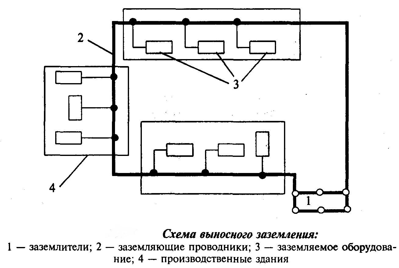
The advantage of this type is the ability to choose the installation site with better soil properties, with a low resistance level. These soils include - clay or sandy wet soil. But there is a significant disadvantage to the method. The value of the tangency of the conductor is equal to 1, because of the distance from the production facilities.
This type of protection is installed to service objects with small short-circuit currents (no more than kV). Potential voltage when touching the damaged section of the circuit is not less than the potential of the earthing switches.
Contouring device
Earthing electrodes are located evenly, along the boundaries of the contour of the serviced section and on it itself. Therefore, the second name of this type is distributed. With this method of installing earthing switches, the safety of using devices is provided by lowering the potentials on each earthing switch and their potentials are equalized. This method allows you to reduce the peak short-circuit current. Earthing devices that are located on the territory of the circuit allow solving this problem.
![]()
Each earthing method, with long operation, can increase the loop resistance. For early detection of a malfunction, it is necessary to periodically inspect the contour and tighten the nuts on the wire fastening.
Arrangement of re-earthing
This method allows you to reduce the dangerous to human value of the fault current and other damage to the wiring and electrical devices. In this case, it is a separate earthing system independent of the main circuit.
The installation provides for the activation of the nearest automatic protection device in an emergency. Most often, in a repeated way, an old building with an obsolete two-wire aluminum wiring is being built. Wiring leads to each consumer from the welding location of the end contact on the basis of the contour. On the body of the shield, the wires are secured with bolts and nuts with groomers.
Types of grounding, depending on the wiring
Before carrying out work on building electrical wiring, it is necessary to make a choice of how to connect the earth wire and the type of protection circuit to the indoor network. Here is the decoding of the abbreviations used in the name of the cable connectors:
- I - isolated wiring;
- N - indicates connection to a neutral wire;
- T - a symbol denoting the connection to the ground wire.
A world grounding system has been adopted, which includes three main types.
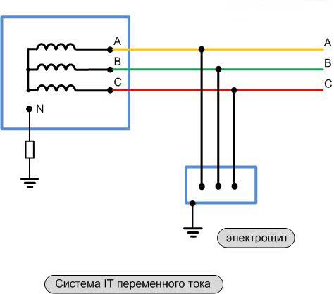
IT system
Practically unapplied system in housing construction. It uses a resistance with a large value or through an air gap. This type of grounding is used in laboratory and treatment rooms. Serves to provide a high level of protection for equipment and appliances that require a significant level of safety and stability in service.
According to the rules of the PUE, for private economic construction, it is possible to use a system with independent earthing switches.
TT system
The wires are led to the panel, at the entrance to the building with two earthing switches. The most often used for maintenance of systems of voltage sources in the network and on the metal coating of the system without insulation. Significant performance of zero wiring at a distance from current transformers to the consumer of electricity.
During installation, there may be a difficulty associated with the selection of the diameter of the wiring to ensure the safety of the earth itself. For this purpose, a shutdown system is installed in this type of wire feed.
TN-system
This, the most common type of grounding conductor with neutral ground wire, allows all current consumers of the building to be connected to the neutral. Connect all equipment to ground via zero wires. All current-carrying housings equipment and devices in electrical switchboards and other consumers, with a short circuit to the enclosure, are disconnected from the network by means of automatic devices and protect a person who is in the room from electric shock. It is divided into the following types:
- TN-5 system. Type of grounding and neutral wire by two separate conductors. This method is by far the safest for humans. The wiring from the power source, with this method, is conducted using a three-core copper wire with an appropriate cross-section for this building and the number of consumers. Typically, a brown or black conductor is used to conduct the phase, zero is supplied with a blue or blue wire, and a yellow-green color of the insulation is used to ground the wire.
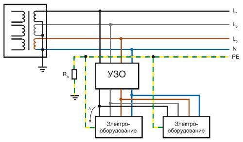
- The TN-C-S system, in which two wires are connected to the electrical panel, namely the neutral wire and the phase wire. And already in the shield produce a division of zero into two conductors, one of which is zero, and the other is the ground wire. To provide reliable and safe protection in the shield, it is required to install an additional circuit breaker after wiring.
When using copper multicore conductors in the wiring of an old building not equipped with a protective circuit, it appears to equip the power grid with a reliable protection.
Such a system well protects wiring and household appliances when lightning strikes. When installing the RCD, the level of human safety increases. By the minuses can be attributed - the installation of additional equipment and reduced security in the maintenance of a country house.
As a result, we give the main points of the article.
The section of the wiring and the choice of the design of the ground loops are one of the main characteristics when mounting one of the types of the ground loop.
Various grounding switches made of artificial or natural metals are used to carry out the work on manufacturing the grounding loop. Proceeding from point 1.7.109 of the installation rules, a reinforced concrete or metal section of a building, cable protective enclosures buried in the well and others can be used.
Do not connect earth wires to gas pipelines, sewage pipes, heating pipes. But to equalize the current potentials, these areas can be used.
If the building's electrical network capacity is more than kW, it must be equipped with a grounding system. Grounding types are used to ensure safe operation of the current network, but the resistance value must not exceed 4 ohms.
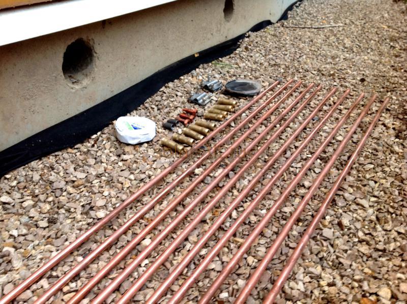
Earthing (grounding pins, plugged into the ground to create a ground loop) are necessarily made of copper, galvanized or ferrous metal. All values of the size of the earthing switches and other components of the circuit are given in the points of the PUE.
The horizontal jumper of the ground loop must be buried at least half a meter into the ground, in case of light soil, it should be at least one meter deep. The horizontal jumpers on the loop resistance are affected more than the vertical earthing switches.
If necessary, a re-installation of the electrical network ground is established.
When selecting a section, it is necessary to familiarize yourself with, but the ground wire can not be less than the phase wire.
Grounding will not be able to replace the automatic circuit breaker and RCDs, and they will not be able to perform grounding operations.