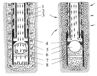
Figure 2.4 - The filter
Figure 2.3 - Schemes of installation of needle filters
a - installation on a foundation pit; b - Single-row installation with narrow trenches;
at - two-row installation with wide trenches; 1- suction manifold; 2-wellpoints; 3 - pumps; 4- Depression curves
The needle filtration unit consists of needle filters, a suction manifold and a pump unit. The needle filters are columns of pipes with a diameter of 50 mm, a length of 8.5 m, in the lower part of which there are filter links (Figure 2.4, a). The filter link (Figure 2.4, b) length of approximately 1.25 m consists of two pipes: an outer diameter of 50 mm with uniformly distributed over the surface of the holes and an internal diameter of 38 mm with an open lower end.
a B C
a - general view of the wellpoint; b - the position of the valve of the filter link when the needlepoint is immersed; at - the same when pumping groundwater;
1 - outer tube; 2 - inner tube; 3 - a filter net;
4 and 5 - rings; 6 - the ball valve; 7 - the rod; 8 - tip
The needle filters are immersed in the ground in a generally hydraulic manner. The collected needle filter with the hose connected to it from the pump is lifted with a crane, tower or tripod and is supported on the ground at the dive site, keeping the wellpoint in the upright position, or lowering it into the previously drilled well. Pump in the needle filter is supplied with water under a pressure of 30-50 m. The ball valve (Figure 2.4, b) under the action of a stream of water drops and opens the hole in the ring 5, and the ring 4 under the influence of the pressure of water rises and closes the gap between the outer and inner pipes. The water supplied by the pump comes out of the tip and blurs the soil, forming a depression into which the needle filter is submerged under the action of its own weight. The suspended particles of the washed out ground together with the water are washed out onto the surface, and the heavy (gravel and coarse sand) remain in the well, forming an additional gravel filter around the filter screen, as a result of which the inflow of groundwater to the needle filter increases.
For better formation around the needlepoint of the gravel interlayer, it is recommended that after dipping the wellpoint, without interrupting the water supply, fill the gravel in the well and only then stop the water supply.
The installed needle filters are connected to a common suction manifold (Figure 2.3) using flexible hoses with union nuts and feedthrough taps. Cranes serve to regulate the flow capacity of the wellpoints and to disconnect individual ones, if necessary, from the suction manifold. The collector is laid with a slope of 0.002-0.005 from the pump.
For pumping out groundwater, self-priming vortex pumps are used, attached to a common collector. During pumping out (Figure 2.4, at) the ball valve rises and closes the opening of the ring 5 , which excludes the possibility of groundwater entering through the needlepoint; movable ring 4 falls on the ring 5, and the water through the filter screen and the holes in the external pipe is sucked by the pump into the inner well of the wellpoint.
The needle filters are mobile equipment for draining the soil within the foundation pit or trench. Distances between the needlepoints are assigned depending on the soil filtration coefficient and the required lowering of the groundwater table. In practice, it ranges from 0.75 to 3 m. The procedure for calculating the flow of water and the required number of wellpoints is given in the relevant regulatory documents.
Light needle-filtration units are designed mainly to lower the water level in soils with a filtration factor from 1 to 50 m / day and when the water stop is at a distance of at least 2-3 m from the bottom of the excavation or trench. At filtration rates of more than 50 m / day, the groundwater level is reduced by means of wells equipped with deep-well pumps.
The number of pumps for pumping out water with decreasing groundwater level is determined depending on the inflow of water to the installation and the number of hooks attached to it. The water is pumped out during dewatering continuously during the entire period of production. To avoid interruption in the operation of pumps and the flooding of excavations with groundwater, emergency backup pumps must be installed. For greater reliability of uninterrupted power supply of energy pumps, it is necessary to have two power inputs from different power sources.
The main requirement for the work on open drainage and artificial lowering of groundwater is the conservation of soil density not only at the base of the structure, but also in the aquifer itself, since the removal of soil particles can cause sediment in the ground. Therefore, there should be no soil particles in the pumped water.
After the completion of the work on dewatering, the needles are extracted from the ground with the help of a crane, tackle or other devices.
When operating the needle-filtration plants, the following basic safety requirements must be observed: the electric motors of the pumps must be grounded, and the switches must be closed; Do not allow dipping and extraction of the needle filters near the wires under current - the distance from them should be such that the raised needle filter in case of falling could not touch the wires.
Lowering the level of groundwater during the development of a trench for pipeline laying is carried out by a gripping system with the subsequent dismantling of individual branches of the wellpoints in the completed sections and transferring them forward in the course of work to subsequent sections.
2.4. Foundation of pipelines
Underground pipelines are laid on the bases, which, depending on the bearing capacity of the ground, can be natural or artificial.
The natural grounds can be most soils, except for unstable (liquefied, quicksand, puchinistyh, with organic inclusions, hacked, bulk, etc.) and frozen. Artificial bases are made in the form of pillows, structures of concrete and reinforced concrete, pile grillage, and also by compaction of soils.
Regardless of the type of foundation, it must ensure the stability of the pipeline and avoid the displacement of stacked pipes in the vertical and horizontal direction.
Pipelines of water supply and sewerage are laid on the natural soil of an undisturbed structure, providing a transverse and longitudinal base profiles specified by the project. Pipes along the entire length should fit snugly to the base. In those cases when, in preparing the basement of the trench, it is opened to an excessive depth, in comparison with the project, it is necessary to make a sandy or uniform filling with the developed soil to the design mark. Subsoil of the soil should be made by layers no more than 10 cm with layer-by-layer consolidation. Pipe laying on loose soils can be carried out only after compaction of the soil to the density adopted in the project. The degree of compaction should be controlled by testing the samples taken. On peat and other weak ground pipes must be laid on an artificial base. When laying pipes on an artificial base, the angle of coverage of the pipe must be at least 90 °.
Natural grounds. Pipelines laid on natural bases must touch them all along at least 1/4 of the part of their cylindrical surface, which is achieved by the arrangement of a ground bed, the shape of which corresponds to the cylindrical surface of the pipe.
Pipes are laid on the foundation, the natural structure of which should not be disturbed (ground checks during digging are not allowed). For this purpose, in the production of excavation by excavating machines, a shortage of soil is left, which is developed manually with simultaneous installation of the bed before laying the pipes. The correctness of the device bed is checked by template.
If, however, in some places, soil recaptures occur or there are boulders at the base of the trench, then sand or local soil is poured into these places with a careful compaction to the state of natural density.
Pipe laying on frozen soils is not permitted, with the exception of dry sandy, sandy loams and gravelly soils.
Natural bases can be laid with concrete, reinforced concrete, ceramic, asbestos-cement, plastic, metal and other pipes. Laying of reinforced concrete pipes of large diameters (1.5 - 3.5 m) must be carried out with the following conditions: in sandy soils (Figure 2.5, a) the pipe bed must cover at least 1/4 of the surface of the pipe (the length of the arc of the pipe supported on the bed must correspond to the central angle of 90 °); in clay soils (Figure 2.5, b), the pipes are laid on sand cushions with a thickness of at least 10 cm (the sand of the pillows is carefully compacted).
In those cases where pipelines are laid in hard (rocky) soils (Figure 2.5, at), it is necessary to arrange a sand cushion with a thickness of at least 10 cm above the projecting irregularities of the base (with careful sealing).
Artificial grounds. Weak dry, as well as aquiferous soils of fine sand with an admixture of silty particles, loess, loess-like loams, ground soils can not serve as substrates for pipelines. In these cases, artificial bases are made, the design of which depends on the nature and water saturation of the soil.
For the laying of pipes in insufficiently stable dry soils on the bottom of the trench, preparation is made of gravel, a gravel-sand mixture or sand with a thickness of at least 10 cm over the entire width of the trench (Figure 2.5, g). The preparation is made with a concrete cushion (chair) in the form of a tray with a height of not less than 0.1 of the outer diameter of the pipe and a thickness of at least 10 cm in the middle. When laying pipes on the concrete surface of the chair, a cement-sand mortar is applied with a layer of 2 to 3 cm.
When the monolithic concrete base is installed, the pipes are laid after reaching the concrete strength of at least 50% of the designed one.
In well-water-bearing aquifers, reinforced concrete and ceramic pipes are laid on a concrete base (chair) located on gravel-sand or crushed stone with a thickness of 20 to 25 cm with a drainage device (Figure 2.5, d).
Figure 2.5 - Piping bases
a– at- natural; g– z- artificial; 1 - reinforced concrete or ceramic pipes; 2 - sand base; 3- clay base;
4 - sand sealed pillow; 5 - rock foundation; 6 - only;
7 - monolithic concrete slab; 8 - gravy of concrete; 9 - crushed stone or gravel preparation; 10 - drainage; 11 - monolithic reinforced concrete slab; 12 - concrete preparation; 13 - reinforced concrete slab grillage;
14 - reinforced concrete piles; 15 - prefabricated plate;
16 - joint of prefabricated elements; 17 - prefabricated reinforced concrete beam of pentagonal section; 18 - reinforced concrete pipes
In water-saturated soils and quicksands, which do not give water well, the concrete base is laid on reinforced concrete slabs, which in turn are placed on crushed stone (Figure 78, e). If water-saturated soils contain organic inclusions or are weak and can cause uneven precipitation, arrange rigid bases in the form of grillage on piles (Figure 2.5, f).
Reinforced concrete pipes of large diameter are laid on the bases of prefabricated reinforced concrete elements - slabs and bars, which are joined together by welding the reinforcing steel produced from them with an embedding of concrete by the joint (Figure 2.5, z).
When pipelines are laid in dry subsoil soils, an artificial base below them can be made by placing a sand cushion in a layer of 20-25 cm on a previously compacted loamy soil. In this case, the trench is developed with a shortage of soil against the design marks of the bottom by 25 to 60 cm. The size of the shortage is established by the degree of compaction of the soily soil. Seal the soil usually with reinforced concrete or cast-iron tamping plates weighing from 0.5 to 3 tons. The required degree of compaction is achieved by impacting the plates 5 to 12 times on one track.
To avoid piping at the joints, backfilling of the pit is performed especially carefully by pouring sand with layered tamping to the state of natural soil density.
The method of laying a pipeline depends in many respects on the material of the pipes, on their mass, dimensions and methods of interconnection.
Sequence of technological operations during laying cast-iron pipelines:
1. Checking the quality of pipes. The pipe is inspected and taped with hammer blows to detect possible defects in the form of cracks, shells and outgrowths. Simultaneously, cleaned from dirt and clogging.
2. Lowering the pipes into the trench. The gasket is always driven from the lowest point upwards, i.e. against the bias. Pipes are stacked so that the fluid flows in the direction from the bell to the smooth end.
The installation of each subsequent pipe in the trench is done by placing its smooth end into the socket of the already laid pipe.
Light pipes (up to 200 mm in diameter) are lowered into the trench manually, and over 200 mm - by installation cranes.
3. Centering in a given direction. When the pipes are joined, the smooth end is not brought to the stop surface of the socket. The resulting annular gap, regardless of the material of the joints, should be for pipes with a diameter of up to 300 mm - 5 mm, and a diameter of more than 300 mm - 8-9 mm. The centering is done so that the width of the socket gap between the outer surface of the smooth end and the inner surface of the socket of the laid pipe is the same along the entire circumference of the circle. Uniformity of the annular gap is achieved by temporarily securing the end of the pipe with wedges, placed in the annular gap at a distance of 30-40 cm from each other along the circumference. The gap between the pipes is checked by the wire hook.
4. Fastening the pipe in place. Pipes of small diameter are fixed by padding the sand in the sinuses to a height of at least 0.5 pipe diameter. Pipes of large diameter, laid on a concrete base, fixed with a chair.
5. Filling of socket joints. Fixation of the socket gap is carried out with a hemp tar or bituminous strand (from the bottom of the bell) with subsequent locking of the asbestos-cement mixture. Instead of hemp strands, rubber cuffs can be used, and instead of asbestos-cement mixture - cement-sand mortar. Recently, mastics became widely used - sealants. It is allowed to use polysulfide sealants for butt joints of sewage pipes. When installing cast-iron socket pipes, the following types of mounting devices can be used: lever-rope, rack with screw grips, rack with two clamps-grippers, with a central end screw.
Concrete and reinforced concrete pipes apply for pressure and non-pressure pipelines.
Butt joints are arranged: bellows with rubber rings, couplings - for pressure pipelines, and for non-pressure ones, the use of seam connections is also possible.
Reinforced concrete and concrete pipes should be inspected before they are laid in a trench to identify possible defects, and also to check their dimensions. Not allowed for laying pressure pipes that have cracks on the outer and inner surfaces of the pipes, detaching the protective layer of concrete, sinks and concrete splits on the bushing end of the pipe and on the inner surface of the bell in the area of the rubber ring.
Installation of the pipeline is performed in compliance with the following requirements:
- straightness in the horizontal and vertical planes;
- density of support on the base;
- the laying is coarse from the bottom upwards along the slope of the bell;
- installation at the beginning of the pipeline section of the deadlock stop;
- providing a gap between the connected pipes.
The gap between joined reinforced concrete and concrete non-pressure spigots up to 700 mm in diameter is 10 mm, more than 700 mm is 15 mm; between reinforced concrete pressure pipes up to 1000 mm in diameter - 15 mm, more than 1000 mm - 20 mm; between rebate pipes on the outer surface of the pipe - no more than 20 mm, on the inside - 10 mm.
Pipes in the layout along the trench should be laid on wooden beds with depressions or nailed down wedges.
The height of the legs should provide a clearance of at least 50 mm to the bottom of the pipe in the socket part.
Before laying pipes in the trench, the foundation marks are checked by leveling.
Installation of reinforced concrete socket pipes begins with putting a rubber sealing ring on the bushing end of the pipe on the edge of the trench. The pipe is lowered in a trench with the help of a crane or a pipe-laying machine. The hub end of the pipe is inserted into the socket previously installed. Then, vertical alignment of the tube is performed using a vizor with simultaneous ground podging under the pipe. Next, the horizontal alignment of the position of the pipe is made over the stockpiles. Further installation consists in rolling the rubber ring into the socket socket with the help of various devices and mechanisms: a tensioning device installed inside the pipe, using a bucket of hydraulic excavator and using a tractor.
After the joint has been assembled, it is necessary to check the correct position of the rubber ring in the mouth of the socket, avoiding twisting it around the circumference of the pipe. In the end, the joint is sealed with cement mortar, which is poured into the joint or zachechenivaetsya. When pouring a hemp rope or rubber cord is applied, gradually introduced into the socket, starting from the bottom half.
When installing reinforced concrete pipes, different ways of connecting pipes can be used with the help of the following mounting devices and mechanisms:
- using a tensioning device installed inside the pipe;
- using a bucket hydraulic excavator;
- with the help of a tractor.
Centering of pipes from the bushing end is performed with the help of wedges, placed in the annular space. The alignment must provide the same annular gap.
After laying and aligning the pipe, it is fixed on the base of the trench by partial padding with soil.
Sealing joints is done with the help of hand caulk. Fixing joints begin with the thinnest of caulk, passing consistently to thicker. At the end of the caulking immediately proceed to the coining of the joints with an asbestos-cement mixture. For zachekanki joints using pneumatic or electric chipping-chased mechanisms.
Installation of ferro-concrete pipes with smooth ends with the help of fixed couplings begins with the lowering of the pipe crane into the trench and installation of a coupling on it. After the pipe is centered, it is ground padded, the working position of the coupling is marked out, and the coupling is lifted. The sealing of the joint is made with a hemp string, then with an asbestos-cement mixture (composition - asbestos fiber 30-35%, Portland cement M 400 - 65-70%, water 10-12% by weight of the dry mixture).
Stacking technology ceramic piping is similar to cast iron.
Before laying in a trench, each pipe is carefully inspected and cleaned of dirt from the inside and outside. If cracks and other defects are found, the pipes are rejected.
Installation of the pipeline is carried out either by separate pipes or by links in two, three, five or more pipes, but the total length of the link should not exceed 8 m. It is particularly advisable to lay the links in wet soils.
Pre-assembly of individual pipes in links is made at the place of their installation. To assemble the links into three pipes or more, make a special template, lay pipes on it and successively seal the joints. If the links are made of two pipes, then one pipe is put up with a bell and the other is inserted with a smooth end into the socket, which is closed in this position. The vertical position of the pipes when sealing the joint is very convenient for operation and provides a high quality joint.
Single ceramic pipes are laid on the bottom of the trench with the help of mounting brackets.
Begin laying from the lower well and lead to the upper (against the slope), positioning the pipes with the funnels forward, i.e., so that the flow of liquid is in the direction from the bell to the smooth end.
Pipes of large diameters are lowered into trenches by self-propelled cranes, and in some cases by mounting tripods or other devices of appropriate load capacity.
The links from the pipes are lowered into the trench by self-propelled cranes using traverses, which ensure the horizontal position of the links when lowering and the safety of the joints.
The lowered pipe or link of several pipes is wound smoothly into the socket of the already laid pipe, leaving a gap of 3-5 mm for pipes up to 300 mm in diameter and 7-8 mm for pipes with a diameter of more than 300 mm. Centering and alignment in the given direction are made in the same way as cast-iron socket pipes.
Butt joints of pipelines from ceramic pipes are sealed with bituminous strand with subsequent locking device from cement mortar, asbestos cement mixture, asphalt or other mastic, and joints of pipelines for aggressive media - materials resistant to this aggressive environment.
At preliminary preparation of links from pipes executed at a trench edge, locks of joints are made from asphalt mastic, and joint locks between links are allowed to be closed with asbestos-cement mixture or cement-sand mortar.
Depth of closing hemp strand take 30 mm, and mastic, asbestos cement and cement mortar - from 25 to 30 mm.
Fixing the joints with a hemp lock and the lock device from asbestos-cement and cement mortar are made as well as the joints of cast-iron pipelines, however, cement joints can only be filled with cement mortar if the ceramic pipes are laid on a concrete or dense base, which does not allow pipe sagging.
Steel pipes can be installed with the laying of pipes with welding in a trench or laying the links of pipes with their welding on the edge of the trench.
Steel pipes are assembled in links in this order:
- Lay down and reconcile the lying;
- stacked with a crane pipe on the bed;
- the edges of the pipes are cleaned and prepared for welding;
- the joints are centered and seized by electric welding;
- joints of pipes with turning of a link of pipes are welded;
- remove the lodges and set the assembled link on the inventory stage.
Before welding the pipes, they must be cleaned of soil, dirt and debris, straightened, and, if necessary, cut off the edges of deformed pipes. In arc welding, the edges of the pipes are cleaned for a width of at least 10 mm.
When installing pipes without a backing ring, the edge displacement from the inside of the pipe must not exceed 3 mm. When assembling and welding pipes on the remaining cylindrical ring, the displacement of the edges from inside the pipe should not exceed 1 mm. When the outer edges of the butt tubes are displaced, a smooth transition from a large outer diameter to a smaller one with a transition angle not exceeding 15 ° must be ensured. If the displacement from the outside of the butt joint does not exceed 5 mm, a smooth transition is achieved due to the oblique arrangement of the surface of the welded seam.
The installation of pipes made with a longitudinal welded seam with pipes with a spiral weld is performed with a displacement of the seams of adjacent pipes by not less than 100 mm. When installing pipes in which the factory longitudinal or spiral seam is welded from both sides, these seams may not be displaced. Pipes should be stacked so that the longitudinal seams are accessible for inspection.
At the junction device with the help of tack welders, the number of them should be: for pipes with a diameter of up to 100 mm - 2 pcs., From 100 to 600 mm - 3-4 pcs., Over 600 mm - potholes through 300-400 mm. The length of the tack must be 15-60 mm for pipes up to 600 mm in diameter and 70-100 mm for pipes with a length of more than 600 mm. The height of the potholders for pipes with a wall thickness of up to 10 mm is not less than 3 mm, and the wall thickness of more than 10 mm is 5-6 mm. When applying the main seam, the tack must be completely digested. Electrodes or a welding wire should be of the same marks, as for welding of the main seam.
For manual arc welding, separate seam layers must be superimposed so that the closing sections of them in adjacent layers do not coincide with each other.
Gas welding of pipes up to 4 mm thick is made in one layer with a thickness exceeding 4 mm - in two layers. Each layer of the seam in multi-layer welding before the application of the subsequent layer is cleaned of slag and metal spatter.
Laying the links of pipes is carried out in the following sequence:
- Folding the link and lowering it into the trench;
- centering of the link and tack of the joints by electric welding;
- alignment of the link;
- padding of the laid link on both sides of the ground to a height of 1/4 of the pipe diameter with a layer-by-layer seal;
- welding of the non-rotational joint of the links.
Insulation of pipe joints consists in cleaning of dirt, dust, scale and rust; primer application; bituminous mastic; wrapping the pipeline with reinforcing and outer wrapping materials.
The primer is prepared by dissolving the bitumen of the same grade in the gasoline as for the protective coating. The bitumen is cooled to 70 ° C. The ratio of the volume of bitumen to the volume of gasoline should be 1: 3, or by weight 1: 1.25 to 1: 2.5. In winter conditions, aviation gasoline is used.
The primer is applied to the dry surface of the pipe. Bitumen-rubber mastic is applied to the dried primer in the hot state (160-180 ° C). The second layer is applied after the first cooling.
With sack paper, waterproofing or briol, the pipeline is wrapped in a hot bitumen coating in a spiral. The wrap must be snug against the primer.
Primer is applied to a dry surface. Bitumen mastic is applied to the dried primer in the hot state (160-180 ° C). The second layer is applied after the first cooling. The paper is wrapped on a hot bituminous coating in a spiral by 2-3 cm, and when using a hydroisol and a breeze, a clearance of up to 2 mm is allowed.
Asbestos-cement pipes are used for laying pressure and non-pressure pipelines. Compared to other pipes, they are very fragile, so care must be taken when loading, unloading, transporting, stacking and installing.
Asbestos-cement water pipes are manufactured by the factory method at a working pressure of 0.6; 0.9; 1.2; 1,5 MPa (correspondingly to the brands VT6, VT9, VT12, VT15) with a diameter of up to 500 mm.
Pipe joints are made with asbestos-cement or metal clutches with rubber rings. The most perfect connection is the connection of asbestos-cement pipes using self-sealing asbestos-cement clutches (CAM) and rubber rings of the shaped section.
Asbestos cement sewer pipes for non-pressure pipelines are made with a diameter of 100-400 mm with smooth ends of 3 and 4 m in length. They are connected by means of sockets, seams with an overlay belt and couplings.
Pipe joints must be strong, waterproof, resistant to corrosion and temperature influences.
Asbestos-cement pipes with a diameter of up to 150 mm are lowered into the trench by a depth of 3 m by hand. Pipes up to 300 mm in diameter are lowered into a shallow trench without anchorages on the straps, and in a trench with a depth of more than 3 m, having fasteners, lowered on a rope or on a soft cable passed through the pipe. Pipes with a diameter of more than 300 mm are lowered into the trench using self-propelled cranes. To lower the pipes use conventional slings or special grippers.
Asbestos-cement pipes are assembled with asbestos-cement clutches and sealed with rubber rings of round section, self-sealing asbestos-cement clutches (CAM) with rubber rings of figured section, flanged couplings with rubber rings of circular cross-section (for pressure pipelines) and cylindrical asbestos-cement clutches (for pressureless pipelines).
Installation of pipelines from asbestos-cement pipes on couplings of type САМ is made in the following sequence. Before the pipes are connected to the contaminated grooves of the couplings, rubber rings are laid so that the cylindrical nests in the rings are facing inside the coupling. When installing the rings into the grooves of the couplings, they must be straightened so that the protruding parts are of the same size along the entire circumference of the coupling.
The device of butt joints with the help of cast-iron couplings is made in compliance with the rules for the arrangement of flange joints, i.e., with the provision of alternately tightening the nuts, so as to prevent the flanges from tilting. Lowering of pipes in the trench, their laying, alignment, etc., are carried out in the same way as for the device of butt joints on the couplings of the CAM.
The connection is marked in the following order:
- at the ends of each pipe, a pencil is marked with a distance equal to half the length of the sleeve minus half the gap between the pipes (these should mark the edges of the sleeve that is pushed to the ends of the pipes).
- at each end of the connected pipes, one more mark is made at a distance equal to half the length of the sleeve plus the thickness of the rubber ring and the cast iron flange. Near these marks, the outer edges of the flanges should be located after tightening the bolts;
- at the end of the marking of the butt joint of the flange, the rubber ring and bushing are installed in accordance with the produced markings and the butt joint is assembled by tightening the nuts in the established order.
The steel bolts, flanges and bushings used in the butt joint device must have anti-corrosion protection (galvanizing, asphalt coating).
Between the pipes to be joined, the ends of which must be cut cleanly perpendicular to the axis of the pipe and processed at the end at an angle of 20-25 °, provide the necessary clearance with a portable rod removed from the pipe after assembly of the joint: 5 mm - for pipes with a passage diameter up to 300 mm inclusive and 8-10 mm - for pipes more than 300 mm. The length of the conical part of the end of the pipe is made equal to: 6-10 mm - for pipes with a conditional pass diameter of 100-150 mm, 12-18 mm for pipes of 200 mm or more. In the interface between the inner surface of the pipes and the ends, roundings or chamfers with a width of not more than 5 mm are allowed.
To ensure that the gap between the pipes after the assembly of the joint was located in the middle of the coupling, marks are made on the pipes at a distance from the ends equal to half the length of the coupling, minus half the gap between the pipes. To reduce friction between pipe surfaces and rubber rings, the outer surface of the pipes is lubricated with graphite-glycerine paste for a length of up to 70 mm from the ends.
Installation of pipes on couplers of the CAM type can be carried out in two ways. At the first - on the stacked pipe push the sleeve up to the mark made on the pipe (20 mm from the end of the pipe), then with the aid of the mounting device, this pipe along with the coupling is moved towards the laid pipeline until the end of the laid pipe goes into the sleeve to the depth 20 mm. To ensure that the coupling does not move from its original mark during installation, a fixed (portable) yoke is installed at its end.
In the second method, a sleeve is projected onto the pipe to be laid over its entire length. Then this pipe is centered with the previously laid, and with the aid of the mounting device, the clutch with the stacked pipe moves to the laid pipe to the mark of 20 mm on it.
In the first and second ways of mounting, the sleeve may initially be superimposed on the laid pipe as well.
For the assembly of butt joints the following devices are used: lever tension jack; the device with the central face screw; lever-and-rack tensioner; screw tension jack.
Among a large number of plastic pipes, polyethylene and vinyl plastic pipes. Polyethylene pressure pipes are made of high and low density polyethylene and are available in four types (L, SL, C and T). Types of pipes differ from each other in the thickness of the walls. The connections of polyethylene and vinyl plastic pipes can be flare, flanged and threaded. They can be combined with welding and glue.
The range of plastic pipes used in the construction of water and sewage networks is shown in Table. 2.7 - 2.9.
Table 2.7 - High-density polyethylene (low pressure) pressure pipes PVP
Bookmark this site
Before installation, to avoid damage to them, the trench and its bottom must be carefully leveled. If there are solid inclusions at the base of the trench, then it is necessary to arrange a sand cushion of sand. Its thickness should be 10-15 cm. With trenchless laying of water pipes, the foundation device and backfilling are not needed.
After the styling is completed, backfilling is performed in the trench. At an altitude of 15-30 cm above the top of the pipe, initial sanding is performed. Subsequent backfilling to the top of the trench can be carried out with local soil of stones or debris larger than 20 mm. Under the roads and driveways that are being designed, the backfilling of the trench is only necessary with sand with a layer-by-layer compaction.
List of necessary tools:
- coupling and welding machine;
- flange;
- compression fittings.
The advantages of polyethylene pipes
Modern polyethylene pipes are made of polyethylene, the brand of which is PE 80 and PE 100 according to GOST 18599-2001. They have many advantages over other types:
- the cost of polyethylene is less than that of steel;
- the period of use is not less than 50 years;
- hDPE pipes are not corroded and very resistant to aggressive media;
- because of the relatively small weight, the installation is carried out without the use of heavy-duty equipment;
- simplicity and reliability in the installation of butt or electrofusion welding;
- the pipe inside does not collapse when the water freezes.
These important properties of polyethylene pipes provided them with wide application in most areas of engineering communications construction.
In order to form and install water supply and drainage networks, it is first of all necessary to use waterways made of polyethylene pipes , taking into account all the advantages of such waterways in front of steel or iron products. An essential flaw in pipes made of metal, especially for steel products, is their short life due to the effects of corrosive processes.
When installing any pipeline system, its performance characteristics will be determined by how carefully and carefully the workers adhered to the technique of installing gutters, of whatever material they were made of - metal or plastic. For each type of pipe there are rules and installation techniques. Laying of pipelines from polyethylene pipes has its own significant differences. First, you need to measure the width of the trench. It should provide excellent convenience for installation and installation of the pipeline. The main thing that must be taken into account is that the width of the ditch should be greater than the diameter of the pipes by about 40-50 cm. Such conditions must be met when laying sewer pipes and when laying water pipes. If the laying of gutters is carried out in strong or dense ground, it is necessary to arrange a sand mound about 10 centimeters wide.
It is extremely necessary to remove from the bottom of the trench any stones, and the bottom must be made smooth and even. It should be ensured that the ground soil on the bottom is not frozen. If the soil for laying the pipeline of polyethylene pipes is loose, then it may be necessary to apply technology to create the effect of strengthening the earth. If there is a probability of soil displacement, geotextiles are laid on the bottom of the ditch to ensure a static position of the water channels in the ground.
The most common installation of a pipeline from polyethylene pipes begins with the laying of a special pillow, which is a kind of material, namely gravel or sand. The thickness of such a pillow can be varied depending on the characteristics of the soil, but on average it is 10-15 centimeters. Seal the pillow only in the vicinity of the manhole. In places where the water pipes are fastened, workers make pits. When the analysis of the soil reveals its ability to strong internal friction, in this case, the pillow can not be stacked. Then, at the base of the track, the hardened soil is seized, and a softer soil is laid out in its place. The seized ground can later be used to fill the pipeline, but it is necessary first to make sure that it does not contain large stones. You can also fill the water supply pipe with sand or fine gravel. First, the backfilling of the pipe is carried out along the entire perimeter, at an altitude of more than 15 cm from its extreme point. If you have to make the soil denser, then fill it in small layers of 20 centimeters. In no case can not ground the ground directly above the drain.
After stacking pipelines made of polyethylene pipes backfilling is most often carried out by the seized land, but it is necessary first to clean it of stones if they exceed 6 cm in size, and if there are boulders, then 30 cm.
Pipes made of polyvinylchloride are fastened together more often by means of glue in the socket. Nevertheless, one must take into account that for gluing it is necessary to scrupulously clean the surfaces and apply the adhesive base very carefully. Do not bend the butt edges. In recent years, for the installation and fixing of gutters made of polyethylene materials, flared spikes have become very popular, which are sealed with rubber cuffs of diverse profiles. In this case, drains are produced with sockets, which contain circular grooves inside. If it is necessary to attach polyethylene pipe to steel or cast iron, then it is necessary to use connections from the flange. Where the sewerage systems are laid from polyethylene gutters through the walls of the wells, fastening couplings with a single ring of rubber are used as casings.
Welding is made mainly by contact method, it is carried out in the socket or butt-end with shaped sections. When welding polyethylene pipes It is necessary to observe very precisely and to monitor the diameter of the drain and their circumference.
Add to bookmarks
Construction of the pipeline from polyethylene pipes
Most of the pipelines laid in the cities are still Soviet-era. Deterioration of heating mains, sewerage, gas and water pipelines reaches 70%, which is due to the material from which the pipes are made. This is steel, which is subjected to intense corrosion attack. The construction of gas pipelines from polyethylene pipes is becoming more in demand today. As the life of the pipeline expires, there are many accidents on various pipelines: pipes are bursting at high pressure, numerous leaks are generated that lead to significant water losses. Operational indicators deteriorate: by reducing the cross-section of pipes, their throughput decreases, water becomes contaminated, and its biological parameters are reduced.
Advantages of polyethylene pipes
Pipes made of polyethylene (PE) are a modern alternative to their outdated physically and morally metallic predecessors. They have a number of indisputable advantages compared to products made of steel or cast iron.
- Absence of corrosive damage, which minimizes the costs of installation, maintenance and repair.
- Ease of use: Polyethylene products are easy to cut, so they are simply customized to fit both on the construction site and in the field when laying pipelines.
- High throughput due to the fact that the internal walls of PE products are smooth.
- Pipes made of polyethylene have an elastic structure of internal walls, on which as a result there is no scaling and they are not clogged from within with various suspensions contained in the liquid.
- Polyethylene is chemically inert, successfully resists aggressive attack, therefore, it does not need additional special protection.
- Polyethylene is not electrically conductive, therefore, wandering currents destroying metal pipes are not dangerous to it.
- The bending radius of the polyethylene pipe can be up to 10 of its external diameters depending on the temperature, which reduces the cost of connecting parts and facilitates the design and construction of pipelines.
- The polyethylene pipe has a high flexibility: the minimum bend radius is equal to 25 pipe diameters at 200 ° C.
- Significantly less weight compared to metal pipes, which facilitates installation and laying.
- PE pipes are resistant to temperature changes and have high sanitary and hygienic characteristics.
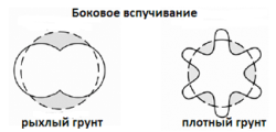
Scheme of deformation of polyethylene pipes depending on the type of soil.
Important note. Freezing of the ground leads to the movement of pipelines in the vertical plane. These displacements are uneven, resulting in deformations (bends). Forecasting these states, determine how much the bending radius of the polyethylene pipe depends on the level of temperature reduction. In order to determine the radius of bending, it is necessary to make special calculations. Alternatively, refer to the special tables, which indicate the minimum bending radius for a particular type of pipe.
Minimum radius bending pipes made of polyethylene is recommended by the manufacturer for each type and grade of pipes. If you do not get the right bend radius, then you should use bends, tees, etc.
Due to their technological and operational characteristics, polyethylene pipes are widely used: they are used for the construction of new pipelines and for repair of old communications that have served their time.
Sphere of application of polyethylene pipes
Polyethylene products are widely used in modern construction.
They are used in the construction of water pipes, sewerage, gas pipelines. PE pipes are used in pressure and gravity sewage, serve as protective cases for electrical and telephone wires.
With the help of polyethylene pipes, old networks are being reconstructed. Replacement can be done with the destruction of worn out communications, but it is possible to lay new ones in parallel with the old ones, which does not require stopping the water supply of the population and shutting down sewerage. Reconstruction of wells and other communication and sanitary facilities depends on the degree of their deterioration. Partial replacement may be subject to separate parts (necks, shut-off valves, etc.), if necessary, major repairs are carried out with a complete replacement of pipelines.
Installation of polyethylene pipes for sewerage
Sewer networks are internal and external. Their purpose is to collect and transport sanitary and storm sewage, which has a different chemical composition. Any problems on the sewerage sharply affect the quality of life.

Elements and assembly for polyethylene pipes of internal sewerage
Polyethylene pipes for sewerage began to be produced not so long ago, and today they fully meet high requirements due to their inertness to the effects of mineral acids, alkalis and other corrosive substances. PE sewer pipes have a high throughput due to the lack of internal roughness. When installing external sewage systems, frost-resistant PE pipes are used. Installation of internal sewage does not require pipes with such high performance characteristics.
Pipes for sewage are attractive for specialists working on the arrangement of such systems in that their installation is much simpler in comparison with traditional sewerage networks. Installation of internal sewerage communications when using polyethylene pipes does not require complicated special equipment. Polyethylene pipes of small diameter are mounted by means of compression fittings.
The equipment of external sewerage is made by a butt welding method: special welding equipment allows for installation, reducing the number of joints up to five times in comparison with metal pipes for sewerage
Connecting polyethylene pipes
PE products are joined in three main ways:
- contact-butt welding,
- socket welding with embedded electric heaters
- installation by means of compression fittings.
A detachable connection is also possible, which is done by steel pressure flanges. Installation of turns and branching of pipelines is carried out with the use of welded or cast fittings.

Different methods of connection are used depending on the working conditions. If there are conditions for placing the welding equipment, then butt welding is necessary. Butt welding is used when working with pipes of large diameters (from 630 mm).
Limited work space (wells, chambers, trenches) requires electromotive welding with embedded heaters.
If it is necessary to connect pipes up to 63 mm in diameter, compression fittings are used, which creates detachable structures. This connection is easy in operation, has high performance indicators, does not require complicated special equipment. The interconnection of internal piping systems is most often carried out by this method. Their installation is available even for non-professionals.
Piping Laying
Laying of polyethylene pipelines is carried out in two main ways. This is the traditional laying of pipes in an open trench and trenchless laying - the method of deep directional drilling.
Pipelines made of polyethylene with an open method are laid in a trench, the width of which is determined by the need to create conditions for work. The water supply and sewerage equipment requires a trench width of 40 cm more than the outer diameter of the pipeline. These parameters are most often written in the project. Long-length polyethylene pipes are often placed in a trench dug with a narrow-chain chain excavator. In this case, the width of the trench is reduced.
The trench should be properly prepared. Its arrangement depends on the condition of the soil. If the bottom of the trench is solid and dense, then a cushion device is necessary. The bottom is covered with a layer (about 10-15 cm) of sand or other granular material and leveled. At a distance of 2 meters from the inspection well, the cushion is rammed. At the bottom there should not be stones, lumps of frozen soil. When working with loose soil, which has a danger of displacement, it is necessary to strengthen the bottom. In such cases, the bottom of the trench is strengthened by geotextile.
With a flat bottom of the trench with optimal soil characteristics, the pillow is not needed. You can do with a small groove of earth at the base of the pipe at its width and replace it with a softer one.
Backfilling of the trench
The soil removed from the trenching device, in which there are no stones of 20 mm in size, is used for primary dumping. It is produced for the entire length of the tube, about 15 cm high from its top. If it is necessary to compact the soil, the soil must meet certain requirements. You can use gravel fractions (20-20 mm) or crushed stone (4-44 mm). The primer can not be dropped directly onto the pipeline. Layed on the bottom of the trench and the sprinkled pipeline needs to be sealed. The buried soil is trampled by layers of 20 cm on both sides of the pipe, so that its displacement does not occur. Directly above the pipe, the ground is not trampled.
Backfill is made after compaction and getting a tamped layer about 30 cm above the pipe. Backfilling of the trench can be done with extracted soil, the size of the largest stones is not more than 300 mm. Even in the presence of a protective layer about 30 cm thick, the size of the stones in the soil used for backfilling can not be more than 60 mm.
Trenchless laying of the pipeline
![]()
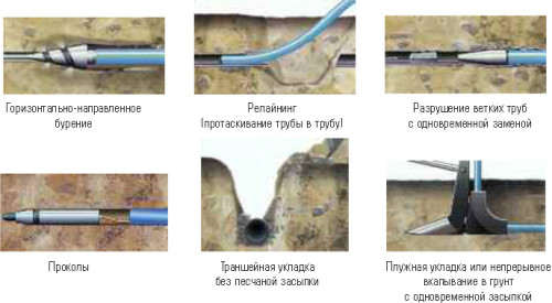
In some cases, when pipeline lines intersect with a railway, a busy transport line, a river and another obstacle, an open trench is not possible. The reason may also be the need to minimize the cost of digging a trench. This is the basis for applying the method of trenchless laying of polyethylene pipelines. The method of trenchless laying of horizontally directed drilling (HDD method) has become widespread.
Horizontal drilling is a special way of communicating without opening the soil. The work begins at the point where the pipe leaves the surface. The technology guarantees a high accuracy of the drill output at the intended site to the surface. The method allows to lay underground pipes with a length of more than 100 m and a diameter of up to 630 mm and more. There are two main ways of horizontal drilling: controlled and uncontrolled.
Controllable horizontal drilling is performed by tunneling machines, through flushing and pilot drilling.
Uncontrolled horizontal drilling is performed by two methods: 1) without casing pipes (ram rocket, displacing drilling, auger drilling) and 2) with casing (drilling, piercing, impact drilling, ram drilling).
Methods of horizontal drilling and trenchless laying of polyethylene pipes are considered the most modern technology. To expand the well, a special drilling extension is used. To improve the wiring, the well is treated with a drilling mud, which forms and lubricates the channel itself.
Thus, the characteristics of polyethylene products allow them to be assembled and laid using any currently known method, taking into account those constraints that impose the minimum allowed radius of their bending.
A dragged or pushed polyethylene pipe is able to repeat the configuration of an old track having a radius of curvature of more than 120 diameters of the pipe itself. Metal products have almost no such bending radius.
Organization of installation works
Welding is carried out either according to the basic scheme, or by the route method. The basic method is used in those cases when the object is located near the welding location, where the pipes are pre-connected, and then their ready sections are brought to the pipeline route. The length of the section can reach more than 30 m. In place, they are welded into a single string, which then carefully, so as not to disturb the radius of bending, should be laid in a trench.
Trench welding starts from the trench. Then, installation and welding by mobile welding units is carried out. Pipes of small diameter can be laid in a trench manually. However, most often used pipelayers or cranes. The ready-made thread should be lowered without jerking, evenly, after fixing it with hemp ropes or soft slings, which should be located at a distance of 5-10 meters from each other. The entire welded thread must be lowered into the trench carefully so that the critical bend radius during the stacking process is not exceeded. Preliminary it is necessary to wait at least 2 hours after welding the last link.
Disadvantages of polyethylene pipes
Problems with polyethylene products are associated with the characteristics of all viscoelastic thermoplastics. Their strength largely depends on the degree of bending and compression, and in general it is relatively small. Polyethylene is sensitive to ultraviolet, which has to be compensated with coloring additives (usually a soot) and the use of protective paint. Thermal expansion of polyethylene is quite high and it must be compensated for by constructive G or P-shaped bending of the pipe.
Today, domestic underground pipelines have a length of about 2 million km. Basically, these are steel pipes. The share of polyethylene pipes, for example, is about 10% of the total length of gas pipelines. Other networks also have not very high rates for this parameter. However, there is a strong trend towards the fact that modern pipelines in percentage terms change in favor of polyethylene pipes.