A heartfelt thanks is due to James King for sharing the history of the development of galvanic voltage sources.
Standard denominations
In the Russian Federation, a mains voltage with an average effective value of 220 V and a frequency of 50 Hz was used. This means that the voltage amplitude is variable, but it can be replaced with a constant equal to 220 V when calculating power consumption and some other parameters.
In addition, 12 V AC light bulbs are widely used in everyday life, which, according to the rules (GOST 50571.11), should be used in bathrooms and restrooms. And constant 12 V reigns among car batteries. Although, in fairness, it should be noted that it is time to send a battery with such a rating to a landfill. The working battery is charged to approximately 14 V.
In the literature one often comes across the concepts of linear and phase voltages. These are also denominations. The first is measured between two phases, and the second between any phase and neutral. For a 220 V network, these figures are respectively equal to 380 and 220 V. These are average effective values, and the amplitude is approximately the root of two times greater.
According to the new standards, the entire country is now switching to a voltage of 230 V. Therefore, neither 380 V nor 220 V can be found in a socket anymore. This is even illegal, because according to GOST the supplier is responsible for the quality of the energy supplied. These steps were taken by the government to ensure smooth operation of imported equipment. But that's not all. In the 10s of the 21st century, the use of incandescent light bulbs began to be prohibited. Increasing the network voltage by only 10% reduces their service life by approximately half. Therefore, violators who secretly used these devices will now pay more often.
Most likely, this is another ploy by officials to get people to buy more. What to do? Go to the whole thing! At the same time, the cost of electricity will be reduced by approximately ten times.
Background
Voltage standard
On July 14, 1729, a great event occurred: Stephen Gray figured out how to conduct static electricity through silk threads and some other materials, creating the first circuit. Before the introduction of electricity, businesses had to be located right on the banks of rivers. Which is not very convenient. It is much easier to build factories where there are resources:
- For a sand quarry - 2 people.
- Street cleaning – 3 people.
- The meat processing plant didn’t send any outfits...
It was difficult to develop natural resources far from energy sources. Human power could not replace electricity. The first attempt to transmit energy over a distance was the commercial telegraph in 1837 with a 20 km line. This proved that it is possible to transmit energy over long distances and perform work there using it. Five years earlier, Sir Joseph Henry had demonstrated a device with a coil of wire a mile long. His electromagnet lifted a very significant load, even by today’s standards.
It should be noted here that everything was done with the help of a voltaic column - a set of circles of copper and zinc, separated by a layer of wet cloth soaked in salt water. The first serious construction appeared in 1836. It became the first rated voltage standard, in which all other sources, such as, for a long time, were measured. John Frederick Daniel tried to solve the problem of the release of gas (hydrogen) by a galvanic source during operation. This led him to the idea of using two electrolytes instead of one.
Daniel was based on a report by Professor Davy in 1801 on the chemical nature of the voltaic column, as a result of the oxidation of one of the metals. Later this topic was touched upon by Becquerel. As for Daniel, he decided to check Faraday's electrochemical experiments and looked for a suitable source for this. As a result, a new type of galvanic cell appeared:
- Original design:
- In the center of the bowl was a zinc rod surrounded by a bovine esophagus. A weak solution of zinc acid was poured inside.
- Around the esophagus was a hollow copper cylinder, 3.5 inches in diameter, filled with a weak solution of copper sulfate. The cylinder was covered with a perforated disk, through which a bull's esophagus and a zinc rod passed through the center.
- On the lower edge of the copper disk there were large crystals of copper sulfate, which prevented the solution from leaving saturation.
- Reconstruction (see figure):
- In the center of the bowl there is a hollow copper cylinder (see figure), immersed in a solution of copper sulfate.
- All this fits inside a membrane made from a bull's esophagus.
- Outside was a hollow zinc cylinder, covered with amalgam and of slightly shorter height, surrounded by a weak solution of sulfuric acid.
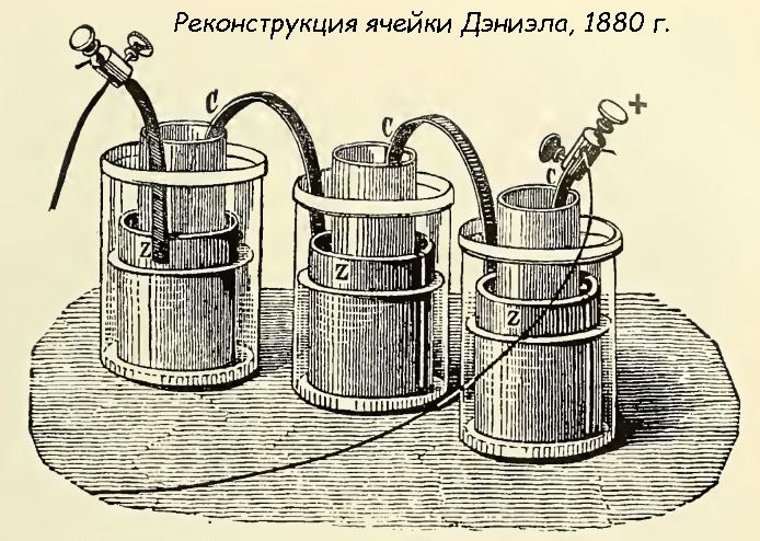
It is unknown what led the scientist to such an exotic design, but it worked amazingly. Although even a hundred years before this scientist would probably have been accused of witchcraft. In 1881, at the International Conference of Electricians, it was decided that the voltage produced by one Daniel cell would be called 1 V. This value is still used today to measure the rated voltage. But with one caveat: the actual potential of the Daniel cell at a temperature of 25 degrees Celsius is 1.1 V.
The designer noted that the bovine esophagus can be replaced with earthenware, but performance characteristics At the same time, the cells became worse. Later, John Gasieux proposed the use of bisque porcelain as a porous membrane. The high internal resistance of the cell resulted in low current, but the constant potential (1.1 V) was quickly noticed, and this galvanic cell was used as a standard until it was officially named as such in 1881. From this time we can start talking about the nominal voltage.
Energy supplies
Already in 1843, Louis Delehuy illuminated the Place de la Concorde in Paris using Bunsen cells and an electric arc. This important point, because, as will be seen later, many other prominent figures of that time looked up to the French shows.
It is believed that the first magneto was built by Pixie in 1832, but the current has not yet found widespread use. In 1844, Woolrich created a pair of hand generators for galvanizing metals, and these were the first industrial designs. In the mid-50s, energy began to be used by obtaining it from steam and converting it into electricity using a crankshaft and similar things. By that time, Page engines were already known, which did exactly the opposite, pushing trains.
The two-ton, 600-rpm engine, built according to Blackwell's design, can be considered the first attempt at creating a fully automatic steam current generator. Paired with it, a mechanical commutator was used to rectify the variable component. In 1858, similar generators began to be used as equipment in English lighthouses. It cannot be said that the result exceeded expectations, but it was the first step towards supplying energy for the needs of mankind.
At the same time, demonstrations of electric lighting were taking place in France. There, the novelty served rather to entertain the public. By the early 70s, some lighthouses had firmly switched to electricity, including the Odessa one. And here the Germans enter the scene. Until now, they remained in the shadow of English and French experiments, so the organizer and entertainer Oscar von Miller wanted to somehow surpass the foreigners. To do this, he ordered to organize the transmission of electrical energy over a distance of 35 miles. Which became the first high-voltage network in the world.
Why do you need to increase the voltage rating?
Section o provides a brief introduction to the development of transmission chains. It was shown that the voltage was constantly being sought to be increased. This is necessary to ensure acceptable efficiency, which today does not fall below 90%. This is explained as follows:
- When current passes through a line, energy is lost.
- This happens according to the Joule-Lenz law.
- The amount of loss is determined by the current...
What does tension have to do with it? According to Ohm's law, these quantities are related. The higher the voltage, the lower the current for the same transferred power. Consequently, the losses are lower. It turns out that when transmitting energy over long distances, the cross-section of the wire must be increased, as well as the rated voltage. So, already in 1923, 220 kV was passed through the line. Throughout the 1920s, the German company RWE AG built such tracks. One of them crosses the Rhine, thrown over two pylons 138 meters high in the Förde area. Since the 1920s, the need to locate enterprises near power plants has completely disappeared.
At the same time, the process of electrification of the United States was underway. The first hydroelectric power station in Niagara was built back in the 90s of the 19th century. And although it was not yet three-phase, Nikola Tesla’s system consisted of 4 wires and could easily be converted. Following the events described, the voltage ratings of transmission lines grew approximately as follows:
- The German line in Rommerskirchen was the first with a rated voltage of 380 kV. In the same year, a similar route, laid through the Strait of Messina, was put into operation in Italy.
- The USA, USSR and Canada simultaneously put into operation lines with a nominal voltage of 750 kV in 1967.
- In 1982, the highest voltage line was introduced between Elektrostal and Ekibastuz. Three phases alternating current rated voltage 1.2 MV.
- In 1999, Japan built the Kita-Iwaki line with a nominal voltage of 1 MV.
Since the beginning of the 21st century, China has taken up the construction of high-voltage lines.
Existing voltage ratings
All long-distance power transmission lines operating today operate at rated voltages from 115 to 1200 kV three-phase current. Further increase in voltage is ineffective because it leads to the appearance of abundant voltages, which tend to develop into an arc. But the biggest losses occur in the low-voltage part. For example, if in France annual losses are estimated at 325 GW hours, which is 2.5%, then in the USA they reach 7.5%. This is explained by the difference in rated voltage - 220 V versus 110.
Today it has been proven that it is more profitable to supply direct current over long distances. Because it does not flow into inductive reactances - capacitive, formed by wire and ground, and inductive. Thus, there is no concept reactive power. This once again proves the fact that Nikola Tesla fought for alternating current mainly to cause damage to Edison.
Taking into account the savings, it may be profitable to build converter stations at the ends of powerful lines to convert one type of current to another. At the same time, losses due to radiation and leakage through the screen into the ground are reduced, and the level of corona discharge is reduced. Already today, cables for recharging submarine batteries are powered by direct current, because it is impractical to transmit alternating current through them already at a distance of 30 km. And today’s lines are 20 times longer and are successfully operated. For AC transmission, restrictions depend on distance:
- On small lines it is heat losses, which should not destroy the wire insulation.
- At medium distances, the voltage drop is taken into account, which should not be too high.
- At long distances, reactive power factors come into force, determining the stability of the system.
Domestic power plants generate three-phase alternating current electricity with a frequency of 50 Hz. Direct current is obtained mainly from converters, so direct current energy is always more expensive than alternating current energy by the amount of conversion cost.
To achieve the best technical and economic performance indicators and provide consumers with electricity, power plants are combined into power systems (district, united, etc.)
The production of electricity depending on the generators used, transmission and distribution depending on the magnitude of the transmitted powers and the distances over which they are transmitted, the use of electricity depending on the electrical receivers used are carried out at different rated voltages.The rated voltage of generators, transformers, power lines, and electrical receivers means the voltage for which they are designed under normal long-term operating conditions, accompanied by the highest technical and economic indicators.
Based on voltage, all electrical installations are divided into two groups: up to 1 kV and above 1 kV.
To coordinate the operation of all electrical installations of power systems, power supply systems - from station generators to power receivers - the rated voltages are standardized. The values of rated voltages for electrical installations up to 1 kV are given in table. 1.1, in table. 1.2 - for electrical installations above 1 kV. For sources and converters, phase-to-phase voltages of three-phase current are indicated.
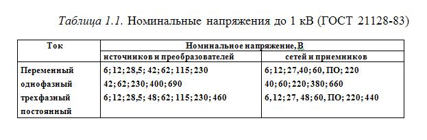
GOST 21128-83 for special purposes provides for the use of additional rated voltages, for example, for electrical networks and current receivers: 24, 42, 127 V.The scale of nominal voltages is determined by the level of development of the national economy and is adjusted over time. Thus, the latest GOSTs introduced voltages of 0.66 and 20 kV, which are more economical for powering large load nodes and power receivers than voltages of 0.38 and 10 kV.
The transmission of large powers over considerable distances necessitated the use of high and ultra-high voltages (500, 750, 1150 kV).
At power plants Electric Energy produced at voltage (3.15); (6.3); 10.5; 21 kV. These rated voltages are called generator voltages.
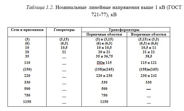
The rated voltages of the secondary windings of transformers supplying electrical networks and the rated voltages of generators are 5... 10% higher than the rated network voltages. This is provided to compensate for voltage losses in lines and transformers.
Important when operating an electrical network is the mode of its neutral, as well as the ability to have linear (phase-to-phase) and phase voltages for electrical receivers up to 1 kV. The neutral of the electrical network is understood as the set of neutral points of the transformer windings (zero potential of the windings connected in a star) and the conductors connecting them. The neutral can be isolated from the ground, connected to the ground through active or reactive resistance, or solidly grounded.
Neutral operating mode selection determined by the reliability and efficiency of electrical installations and the safety of their maintenance. Electrical installations with voltages up to 1 kV are performed with an insulated or solidly grounded neutral.
Solid grounding of the neutral can be carried out at voltages of 220/127, 380/220, less often - 660/380 V. The neutral wire in a four-wire network ensures equality of phase voltages with uneven loading of phases from single-phase electrical receivers. Three-phase networks with a grounded neutral allow you to power three- and single-phase loads together, for example, three-phase - at a linear voltage of 380 V, single-phase - at a phase voltage of 220 V.: Installations with an isolated neutral are used in conditions with increased safety requirements (peat mining, coal mines, mobile electrical installations), Electrical installations with voltages above 1 kV according to the type of neutral mode are divided into: electrical installations in networks with an effectively grounded neutral (with high ground fault currents); in networks with an isolated neutral (with low ground fault currents).
In electrical networks with voltages of 110 kV and above, effective neutral grounding is used. An electrical network with an effectively grounded neutral is a three-phase electrical network above 1 kV, in which the earth fault coefficient does not exceed 1.4. The earth fault coefficient is the ratio of the potential difference between the undamaged phase and the earth at the point of earth fault of another (or two other) phase to the potential difference between the phase and the earth at this point before the fault.
Electrical networks with a voltage of 6-35 kV are made with isolated or compensated, i.e. connected, for example, through inductance (arc extinguishing coil), neutral.In networks with an isolated neutral, during a ground fault, capacitive currents will flow through the fault location, determined by the voltage and capacitance of the undamaged phases. The inclusion of active or reactive resistances in the neutral is caused by the need to limit capacitive currents to the ground. Thus, these currents should not exceed in normal modes: in 3-20 kV networks with reinforced concrete and metal supports on overhead lines, and in all 35 kV networks - 10 A; in networks that do not have reinforced concrete and metal supports on overhead lines: at a voltage of 3-6 kV - 30 A, at 10 kV - 20 A, at 15-20 kV - 15 A.
In networks with isolated neutral, the following must be taken into account.
1. When the phases of a three-wire electrical network are unevenly loaded, a neutral bias voltage occurs, and each of the phases will be under a voltage different from the phase one. This is especially important to consider for networks with voltages up to 1 kV.
2. A short circuit of one phase to ground is not considered an emergency, but only an abnormal condition. When it occurs, the network and the damaged line may remain on and continue to operate for some time. A ground fault has virtually no effect on the phase-to-phase voltage system and the operating mode of electrical receivers. This increases the reliability of power supply to consumers.
3. When one phase is shorted to ground, the voltage of the other two phases relative to ground increases by l/3 times. In this regard, insulation of all phases is provided for line voltage. At voltages up to 35 kV, this does not cause a significant increase in the cost of the network.
4. At high single-phase currents, the arc at the short circuit burns steadily and for a long time, causing overvoltages that are dangerous for the insulation of undamaged phases, and the transition of a single-phase short circuit to a phase-to-phase one.
When the neutral is solidly grounded, any short circuit of one phase to ground is a single-phase short circuit and should lead to the activation of protective devices that disconnect the damaged section from the network.
Power supply systems are constructed at several voltages. The criterion for an optimally adopted power supply system is the minimum reduced costs for its construction and subsequent operation. The costs of constructing a power supply system are largely determined by the number of voltage transformations and the rated voltages used. Typically, power supply systems use 2-3 voltage transformations.
Page 1
Rated voltage is a certain conditional (basic) voltage from a standardized range of voltages that determines the insulation level of the corresponding element of electrical equipment.
The rated voltage at the output of the M-DM amplifier is 1 V. The voltage from the M-DM amplifier is supplied to the differential input of the output amplifier, which makes it possible to reduce the load of the clamping circuit due to the high input impedance of the amplifier on the differential input side.
The rated voltage of a three-phase electrical machine is its phase-to-phase (line-to-line) voltage.
The nominal voltage of 600 V is set using potentiometer R109 and controlled by an AMB voltmeter on a 600 V scale.
The rated voltage of 150 V is set using potentiometer R61, the voltage is controlled by an AMB voltmeter on a 300 V scale. The VOLTAGE CONTROL switch is in the 150 V position. The indicator arrow should be against the red mark.
| Primary sectional cabinet. |
Rated voltages for cables manufactured according to existing modern technology And production practices are well above the upper limit that can be used for local underground distribution systems. However, the size and complexity of splicing cable branches must be taken into account when using higher voltages. Currently, branch couplings for voltages up to 37 kV are in operation and couplings at higher voltages are being prepared for commissioning. In some locations, non-standard underground transformers with higher primary voltages are used.
| The transformer tank is the same type as shown in.| The transformer tank is the same type as shown. |
The voltage rating for this cable is typically 600V. The insulation is of a heat and moisture resistant type in accordance with IPCEA standards.
The rated voltage of all circuits is 220 V for all stacks.
The rated voltages on their electrodes are usually indicated on the receiver circuits, in the recommended operating modes of electronic tubes, or determined by their characteristics. The mode of multigrid lamps is, in addition, determined by the voltage values on the second and third grids. To ensure the desired mode, you must first make sure that the blocking capacitor of the second grid is working properly, and then select the resistance of the quenching resistor or change the lamp. A significantly smaller voltage spread on the second grid when replacing a lamp is usually obtained when the second grid is powered from a voltage divider.
Rated voltage is the conditional voltage value at the terminals of a freshly charged battery at the beginning of its discharge with current, the value of which is established by GOST or TU.
The rated voltage on the inductor and capacitors is equal to the linear or phase voltage, depending on the connection diagram of the motor windings. To obtain large starting torques, a starting capacitance is used. Scheme Fig. 5 - 21, in is used in cases where it is necessary to connect a motor with a phase voltage of 220 V to a single-phase 440 V network. During the acceleration of single-phase capacitor motors, the parameters of the capacitor banks must change in proportion to the change in motor parameters.