In order to slightly dilute the reviews of swimsuits, I’ll tell you about my experience in building dynamic backlighting for a TV. stop making habr out of musk
Main part backlight is still an LED strip, so I decided to put it in the title. although few more components were involved in the construction.
If you have long wanted to attach a backlight to your non-Philips TV, but were afraid to try, try it. it's easier than it seems.
For starters, a short video of the result.
At the moment - the backlight works even more cool - in the settings I set the brightness to higher and the refresh rate higher, now in action films or scenes in a club (when there are strobe flashes in the frame) - the whole wall simply explodes with light
How it was done was quite simple:
+
+
+
A little courage=
Ambilight
In more detail on the points:
1 I already had Malinka at that time. I bought it there on Amazon, but I think the origin doesn’t play a role here - the board is unified and you can buy it absolutely anywhere - the main thing is that I don’t recommend buying a used one. After some time of working at the maximum frequency without additional radiators, it started to glitch. I chalk it up to overheating, but it could also just be a manufacturing defect. Raspberries are extremely sensitive to the power source, so immediately stock up on a normal power supply with a low ripple level... (and so that it does not sag under load)
2 The actual tape. I think it works quite well in the video. There is nothing special in the tape itself; I cut off pieces so that there was enough for exactly 3 sides of the TV. I soldered the bends with pieces of wire (initially I made the connection using connectors, but I quickly got annoyed that there were long pieces of wire sticking out - I cut everything and soldered it in small pieces)
3 The ingenious hyperion program. Installed on Raspberry (I have multimedia OpenElec as my OS) according to instructions for idiots. I even got it right the first time. During operation, it stupidly captures color data from the edges of the screen, averages it and sends control signals to the LED strip. The tape flashes with all the colors of the rainbow, the audience is delighted. During operation, when playing fullHD weighing 30 gigs, the additional load on the percent is 5-10%. Doesn't affect speed in any way.
The result exceeds our wildest expectations:
with an LED density of 30 tons per meter, the entire wall behind the TV (about 10-15 centimeters away) is colored in the colors of the screen. visually the stage moves apart... well, as much as there is this very wall. There is no delay in transmission. at least impossible to track with the eye. everything is smooth and clear. There is a cool program for a smartphone with which you can switch the backlight to lounge mode - set the desired color/brightness, or launch one of the proposed patterns (such as a running red light, or just a rainbow, or, for example, color transitions).
When the backlight is turned off while watching cartoons, my daughter is indignant and demands to return everything back.)))
Well, in order to comply with the MySKU policy, a review of the parts itself:
LED strip - reviewed many times. I got exactly the same one. Very good. the quality is excellent. displays, if memory serves, 16 million shades. I didn't count it exactly. requires additional power - I hung plus minus on the 5V 2A block - more than enough for 2 meters. I think it will be enough for 3, but I won’t guarantee it. I connected the control contacts to the GPIO of the raspberry. 
Malinka is a single board computer. Not seen only by the lazy. A great thing both for mastering the basics of Linux and for building a minimalistic and flexible media center. It turned out to be an ideal option for me: it scrolls through any content available to me, works as an Internet TV receiver, pretends to be the recipient of an AirPlay signal when I want to launch something from my phone or laptop. Great thing - 3 watts and a lot of fun + HDMI CEC support out of the box - everything is controlled from the original TV remote control.
And finally, one more video to follow:
A couple of days ago I decided to make more demovidos, already in a new apartment.
The color of the wall is pistachio, I haven’t changed the settings and won’t. so the colors lean a little green. I like it and I don’t care about your opinion)
I'm planning to buy +69 Add to favorites I liked the review +16 +48
What is Hyperion Ambilight
A backlight technology for televisions that was invented and patented by Philips Electronics.
It is a backlight that, analyzing the color image of the frame on the TV screen, reproduces diffused light around the perimeter of the TV. Thanks to this, the surface of the wall behind the TV body is dynamically illuminated, thereby adding a halo to the intensity of the image on the screen itself and visually increasing the size of the image.
1. Basic iron
Since the technology is patented, we will not see it on TVs other than the Philips brand for many years. By the way, I owned such a TV, with three-sided backlighting, but it was so slow that I sold it 6 days after purchase. Well, we'll have to do it ourselves... For this we will need:
- Raspberry Pi 3 link ($42)- just take the latest version of Raspberry, if you plan to use it as a media server, then I advise you to take something more powerful, for example Asus Tinker Board . If you have a Raspberry Pi 2 lying around, then everything will work well on it, without any delays.
- LED strip APA102 link ($8/meter)- there are only two options, either take the original APA102, or its analogue SK9822, which is cheaper, but works exactly the same. I'm using analog. I advise you to take Black IP67 30/meter. IP67 comes with silicone protection, which does not turn yellow over time and protects against dust and interference. Regarding the number of diodes, 30 per meter is quite enough, and the power supply can be found in a “laptop” version. Take the TV on all 4 sides, even if it is on a stand. A 48-inch TV requires exactly 3 meters of tape. I recommend taking all the necessary tape at once from one seller and in one order, since different batches of tape may have different shades, this will hurt the eye. Never believe that a system can be built on ws28*, just look at the characteristics:
I had an extremely sad experience with the ws2801 tape: firstly, it is frankly slow, it does not have enough refresh rate, secondly, the white is not white, you need to adjust it, thirdly, the diodes constantly blink randomly, fourthly, they simply fall off Fifthly, chips from this tape must be soldered.
- Power supply 5V 8A link ($11)- the choice of block depends on the configuration of the tape, I’ll just give my calculation example: a tape of 30 diodes/meter consumes 9W per 1 meter (in cases when white is on, in reality it is much less), we count to the maximum: 9W * 3 (number of meters) + 20% reserve = 32.4 W, the power supply produces 5 * 8 = 40 W is quite suitable, and all other devices can be powered from it.
- Connectors- P Let's not say, why complicate things, let's take and order some connectors:
2. Iron assembly
We assemble according to the following scheme. It is important to energize the beginning and end of the tape so that the glow is uniform. Be sure to connect the power supply of the tape to the common ground. To avoid possible signal interference, you can use ferrite filters, but I did it without them and no problems were found.
We try it on, cut it, connect it with corners, glue it.
The LED strip comes with a standard adhesive base - the strip does not stick to it and will fall off quickly. I bought foam adhesive tape for attaching mirrors at a construction hypermarket. Be sure to degrease the surface of the TV. The TV body can be rounded; it becomes possible to stick the tape at an angle so that the diodes shine more on the sides, but I do not recommend doing this. It is worth sticking the tape strictly perpendicular to the wall. The ideal distance from the wall is 15cm-20cm. In my case, it turned out to be 24cm, due to the shape of the TV stand.
The raspberry can also be glued to the back of the TV. I glued it with Velcro from clothes so that I could remove it.
I read that this scart adapter does not work on all TVs, but I advise you to try it, it’s cheap. The adapter must be set to OUT mode.

The backlight works from the USB connector of the TV, turns on/off along with the TV and the brightness can be adjusted.
For production you will need:
- White LED strip 12-24 volts (color tone to taste);
- Voltage-increasing module MT3608 (costs 29 rubles in China);
- USB "plug";
- a few wires;
- soldering accessories;
- Voltmeter;
- Ammeter;
- all sorts of little things.
Manufacturing process
First, we measure the size of the TV and figure out how to place the tape, cut off the required amount.

We solder the resulting 4 pieces of tape with flexible wires. Be sure to observe polarity.

The backlight will be connected from the USB connector of the TV, but there is only 5V and this is not enough for us. To operate LED strips you usually need 12 or 24V. Therefore, we use the MT3608 voltage-increasing module; it will increase the voltage from 5 to 12V. We solder the wires from the USB “plug” to the module input (VIn).


We sing the tape to the output of the module.

In principle, it should already work =)
To be able to regulate the brightness, I glued a “swivel” with a piece of a match to the variable resistor regulating the voltage (the “bum option”), thanks to this the resistor can be turned forward and backward only half a turn. The extreme positions will correspond to the minimum and maximum brightness; you select them yourself. (the yellow thing on the board is a tantalum capacitor; it reduces voltage ripple at the output and is unnecessary, ripple is already minimal).

After everything is assembled, you must check the current consumed by the circuit at maximum brightness; for this you can use a USB voltammeter or, in my case, a laboratory power supply. The voltage on the tape should not be higher than the nominal voltage.

The current should not exceed the maximum permissible for the connector.

After all the checks, we unstick the tape and glue the module onto the adhesive tape.


All is ready! enjoy

Finally
It is not necessary to do it exactly as I did and I did not invent the wheel.
You can make everything neater and more beautiful
The backlight does not overheat and does not blink, the conversion frequency is about 1.2 MHz
I am not responsible for a broken TV or work-related injuries, please be prudent and careful.
You can buy a 5V LED strip and dispense with the voltage-raising module.
You can use an RGB strip + remote control module if you want a remote control and special effects, but this will quickly get boring.
If the power of the USB connector is not enough, then you need to connect a 5 volt relay instead of the strip and through it turn on/off together with the TV not only the backlight, but also any other equipment plugged into the outlet, for example, acoustics.
Below is a project for making an Ambilight backlight for a TV or monitor. The previous article, "Dynamic TV Backlighting," used a simple approach using four RGB LED strips, allowing only one color to be displayed on each side of the TV.
In this article, we will improve our lighting by using RGB LED pixels, which allow us to control each RGB LED. Read more here: .
So what we need:
- digital tape based on the new WS2801 controller. One such strip (25 LEDs) is quite enough for a regular average monitor. The distance between the RGB modules is about 10 cm. For a large TV you may need 2 of these strips
- stabilized 5V power supply for powering RGB LED. The maximum power supply current must be selected based on the power consumption of RGB LED modules. If one strip (25 RGB LED) is used, then the power supply current is needed 1.5A, if 2 strips, then 3A, respectively.
- Arduino controller, connectors and other little things.
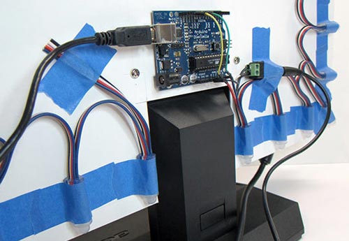
To facilitate connection to Arduino and PSU with tape, minor modifications were made. For the data and clock lines of the tape, connecting connectors were soldered so that they could be securely inserted into the Arduino connectors. To connect the power supply, a connector was soldered. A common ground was soldered from the connector to the Arduino. In the photo below, I think everything is quite clear:
In Arduino, the 13th pin was used for clock, and the 11th pin for data. Plus, don't forget the "ground".
Now, we need to decide how all this will be mounted on the back wall of the TV or monitor. There are many options here, and you can simply attach the LEDs with tape to the back of the monitor, or you can cut out a beautiful template or plexiglass. Our template would be made of thin plastic, with all the necessary cutouts for the monitor and mounts:
Then, you need to evenly space the 25 RGB LEDs. I got a distance between the LEDs of about 50mm.

When making the template, do not block the ventilation holes on the monitor, if any.
After all the RGB LED pixels are attached, all that remains is to attach the Arduino controller. Double-sided tape is best suited for these purposes. We connect the USB cable to the Arduino and the 5V power supply to the RGB LED strip.
Software
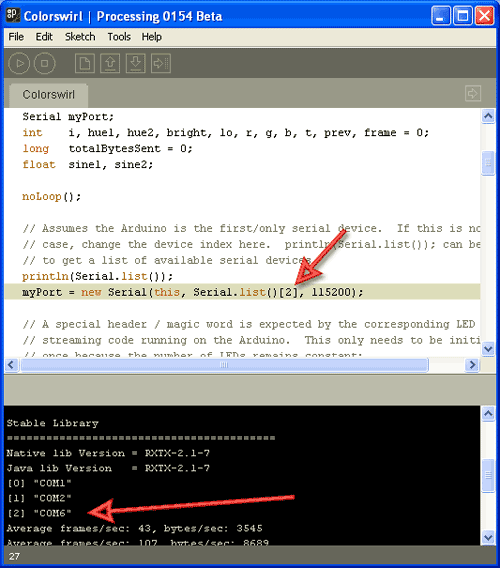
You can download all the necessary software from GitHub. In the Arduino->LEDstream folder there is a sketch for Arduino. Compile it and load it into the controller.
The computer uses software for the Processing IDE, which must be downloaded and installed separately (not to be confused with Arduino Processing!). If your configuration does not have 25 RGB LEDs, then changes will need to be made to the sketch. Also, you need to select the COM port to which the Arduino controller is connected to transfer data (see screenshot below).
The program works as follows: after launch, the program runs in the background and constantly takes screenshots of the screen and analyzes the colors of individual points around the perimeter. Then it calculates the average color for the points and transmits the data to the Arduino controller. And it doesn’t matter what is running on the computer - a media player, a browser with a YouTube video, or something else.
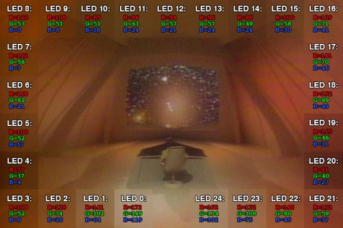
We will not consider the program code, because... it is well commented. By the way, in the Colorswirl folder there is a small example of a demo sketch that displays a rainbow on RGB LEDs.
Some old hardware may not be able to cope with the load (for example, the first Atoms on netbooks), because screenshots are constantly being taken. In this case, reducing the resolution, for example 800x600, can help.
In 2007, Philips patented an incredibly simple, but, without exaggeration, amazing TV backlight technology. With such adaptive backlighting, the eyes become less tired when viewing in the dark, the presence effect increases, the display area expands, etc. Ambilight is applicable not only to video and photo content, but also to games. Ambilight has become a hallmark of Philips TVs. Since then, Philips has been closely vigilant so that none of the major manufacturers would even think of encroaching on the sacred by creating something similar. It is probably possible to license this technology, but the conditions are somehow prohibitive, and other market players are not particularly eager to do this. Small companies also tried (and there are now companies that are doing this) to introduce similar technology in the form of separate kits, but punishment from Philips was inevitable. So, in the best case, if the company does not somehow renew the patent or its derivative, other manufacturers will only be able to produce something similar in 2027.
But such punishment does not apply to us, ordinary consumers. We are free to do what we see fit. Today I will tell you in detail how to make your own adaptive backlight for a TV or monitor like Philips Ambilight (hereinafter simply Ambilight). For some, the article will not contain anything new, because... There are dozens of such projects, and hundreds of articles have been written in different languages, and there are thousands of people who have already done this for themselves. But for many this can all be very interesting. You don't need any special skills. Only basic knowledge of physics for the 8th grade of high school. Well, just a little bit of soldering of wires.
So that you can better understand what I’m talking about, I’ll give you my example of what happened. The real costs for a 42" TV are about 1000 rubles and 2 hours of work.
The video does not convey all the sensations and effect in its entirety, but the children sat with their mouths open for the first time.
Possible implementation options
There are several options for implementing Ambilight. They depend on the video source.The cheapest, simplest and most effective option is a PC running Windows, Mac OS X or Linux as the signal source. Windows boxes on Atom processors, which cost from $70, are now very common. All of them are ideal for implementing Ambilight. I’ve been using various Windows boxes (in a TV stand) as a media player for several years now, I’ve written a small handful of reviews and consider them the best TV set-top boxes for media content. The hardware implementation of this option is the same for all of the listed operating systems. It is this option that I will talk about in the article.. The software part will be related to the Windows system; AmbiBox will act as a universal control program. Can be used with Mac OS X and Linux.
The second option is that the signal source is a media set-top box based on Android, of which there are also a huge number. This option is the most problematic. First, the highlighting will only work in the Kodi media harvester (and its offshoots). Secondly, in the vast majority of cases, everything works only with hardware video decoding disabled, which is unacceptable for most boxes. The hardware implementation of the project also imposes certain requirements. I won’t touch on it, but if there’s something specific you’re interested in, I’ll try to answer in the comments.
The third option is a solution independent of the signal source. This is the most expensive, but absolutely universal solution, because... the signal is taken directly from the HDMI cable. For it you will need a fairly powerful microcomputer (such as a Raspberry Pi), an HDMI splitter, an HDMI-RCA AV converter, a USB 2.0 analog video capture device. Only with this option you can be guaranteed to use Ambilight with any TV set-top box/receiver, Android boxes, Apple TV, game consoles (for example, Xbox One, PlayStation 4) and other devices that have an HDMI output. For the version with 1080p60 support, the cost of components (without LED strip) will be about $70, with 2160p60 support - about $100. This option is very interesting, but a separate article needs to be written on it.
Hardware
To implement it, you will need three main components: a controllable RGB LED strip, a power supply, and an Arduino microcomputer.First a little explanation.
WS2811 is a three-channel controller/driver (chip) for RGB LEDs with single-wire control (addressing an arbitrary LED). WS2812B is an RGB LED in an SMD 5050 package, which already has a WS2811 controller built into it.
For simplicity, the LED strips suitable for the project are called WS2811 or WS2812B.
WS2812B strip is a strip on which WS2812B LEDs are placed in series. The strip operates with a voltage of 5 V. There are strips with different densities of LEDs. Usually it is: 144, 90, 74, 60, 30 per meter. There are different degrees of protection. Most often these are: IP20-30 (protection against solid particles), IP65 (protection against dust and water jets), IP67 (protection against dust and protection against partial or short-term immersion in water to a depth of 1 m). Backing in black and white.
Here is an example of such a tape:

WS2811 tape is a tape on which a WS2811 controller and some kind of RGB LED are placed in series. There are options designed for voltages of 5 V and 12 V. Density and protection are similar to the previous option.
Here is an example of such a tape:

There are also WS2811 “strips” with large and powerful LEDs, as in the photo below. They are also suitable for implementing Ambilight for some huge panel.

Which tape to choose, WS2812B and WS2811?
An important factor is the power supply of the tape, which I will talk about a little later.
If you have a power supply at home that is suitable for power (often power supplies are left at home from old or damaged equipment), then choose a tape based on the voltage of the power supply, i.e. 5 V - WS2812B, 12 V - WS2811. In this case, you will simply save money.
From myself I can give a recommendation. If the total number of LEDs in the system is no more than 120, then WS2812B. If more than 120, then WS2811 with an operating voltage of 12 V. You will understand why this is so when it comes to connecting the tape to the power supply.
What level of tape protection should I choose?
For most, IP65 is suitable, because... On one side it is coated with “silicone” (epoxy resin), and on the other there is a 3M self-adhesive surface. This tape is convenient to mount on a TV or monitor and is convenient to wipe off dust.
What LED density should I choose?
For the project, strips with a density of 30 to 60 LEDs per meter are suitable (of course, 144 is possible, no one prohibits). The higher the density, the greater the Ambilight resolution (number of zones) and the greater the maximum overall brightness. But it’s worth considering that the more LEDs in the project, the more complex the strip’s power supply circuit will be, and a more powerful power supply will be needed. The maximum number of LEDs in a project is 300.
Buying tape
If your TV or monitor is hanging on the wall, and all 4 sides have a lot of free space nearby, then the tape is best placed at the back along the perimeter on all 4 sides for maximum effect. If your TV or monitor is installed on a stand, or there is little free space at the bottom, then the tape should be placed on the back on 3 sides (i.e. the bottom without tape).
For myself, I chose a white WS2812B IP65 strip with 30 LEDs per meter. I already had a suitable 5V power supply. I was deciding whether to use 60 or 30 LEDs per meter, but chose the latter after reviewing the video with ready-made examples of implementation - the brightness and resolution suited me, and the power supply was easier to organize and there were fewer wires. Aliexpress has a huge number of lots of WS2812B tapes. I ordered 5 meters for $16. For my TV (42", 3 sides) I only needed 2 meters, i.e. I could buy it for $10, the remaining three meters for a friend. Prices often change among sellers, there are many offers, so just choose a cheap lot on Aliexpress with a high rating (search keywords - WS2812B IP65 go WS2811 12V IP65).


Buying a power supply for the tape
The power supply is selected according to power and voltage. For WS2812B - voltage 5 V. For WS2811 - 5 or 12 V. The maximum power consumption of one WS2812B LED is 0.3 W. For WS2811 in most cases it is the same. Those. The power supply power must be at least N * 0.3 W, where N is the number of LEDs in the project.
For example, you have a 42" TV, you chose a WS2812B strip with 30 LEDs per meter, you need 3 meters of strip on all 4 sides. You will need a power supply with a voltage of 5 V and a maximum power of 0.3 * 30 * 3 = 27 W , i.e. 5 V / 6 A. My implementation uses only 3 sides, a total of 60 LEDs (57 to be precise) - power from 18 W, i.e. 5 V / 4 A.
I’ve had the ORICO CSA-5U (8 A) multiport USB charger lying idle for a long time, left over from an old review. Its ports are powered in parallel (this is critically important), this charger is ideal for me as a power supply, because... I will connect the tape through 2 parallel connections (explanations will be later in the article).

If I didn’t have this charger, I would have chosen it (there is information that this particular power supply is equipped with 2.5 A internals, so you need to study this issue in more detail with the seller, or look at other models).

Buying a microcomputer
Ambilight will be controlled by an Arduino microcomputer. Arduino Nano on Aliexpress costs about apiece.

Costs for my option (for 42" TV):
$10 - 2 meters WS2812B IP65 (30 LEDs per meter)
$4 - 5 V / 4 A power supply (I didn’t spend any money on a power supply, I’m giving the cost for clarity)
$2.5 - Arduino Nano
-----------
16,5$
or 1000 rubles
Hardware implementation
The most important thing is to properly organize the power supply for the tape. The tape is long, the voltage sags at high currents, especially at 5 V. Most of the problems that arise for those who make their own Ambilight are related to power supply. I use the rule - you need to make a separate power supply for every 10 W of maximum power consumption at 5 V and 25 W of power consumption at 12 V. The length of the power supply (from the power supply to the tape itself) should be minimal (without reserve), especially at 5 IN.
The general connection diagram is as follows (the diagram shows the power connection for my version):

Power is supplied to the tape at both ends - two parallel connections. For example, if I were lighting on all 4 sides, and the strip had 60 LEDs per meter (i.e. maximum power 54 W), then I would make the following power supply:

The connecting wires must be used appropriately; the smaller the gauge (AWG), the better, so that they are sufficient for the calculated current strength.
Two contacts go to the Arduino from the tape. GND, which needs to be connected to the corresponding pin on the Arduino. And DATA, which needs to be connected to the sixth digital pin through a 300-550 Ohm resistor (preferably 470 Ohms). If you don’t have a resistor, then in most cases everything will work fine without it, but it’s better to have one. You can buy a resistor for a couple of kopecks at any radio store. The Arduino microcomputer itself can be placed in any convenient case; many people use a Kinder surprise egg for this. The Arduino should be placed as close to the tape as possible so that the DATA connection has a minimum length.
Soldering wires to the tape is simple. The main rule is that the contact time with the soldering iron should be minimal; you cannot “mess around” with the soldering iron.
In my case it turned out like this:


Two black high-quality USB cables were used for power, and a white one for connecting to the computer. I ran out of white heat shrink tubing so I used red ones. Not as “pretty”, but it suits me (it’s hidden behind the TV anyway).
An important question is how to bend the tape at a right angle? If you have a strip of 60 LEDs, then the strip needs to be cut and connected with short wires (placing it all in a heat-shrinkable tube). You can buy special three-pin corner connectors for LED strips (there are 4 pins in the picture, just for example):

If you have a strip of 30 LEDs, then the distance between the LEDs is large, you can easily make a corner without cutting. Remove a piece of the “silicone” coating, insulate (you can even use tape) the contact pad and bend it according to the diagram:
I cut a piece of tape to practice. The main thing is not to overdo it - bend it slightly once and that’s it. There is no need to bend it here and there, there is no need to press the bend line too hard.

Here is a view from the back of the TV, all the wires go through the hole into the cabinet:

Software part
This is the simplest thing.We connect the Arduino microcomputer via USB. The driver (CH340 serial interface) will be installed automatically. If this does not happen, then in the Arduino IDE folder there is a Drivers folder with everything you need.
Launch the Arduino IDE and open the Adalight.ino file.

We change the number of LEDs in the code. I'm 57.

Tools > Board > Arduino nano
Tools > Port > Select the COM port (the desired option will be there)
Click the “Download” button:

The program will inform you when the download is complete (this is literally a couple of seconds).
Ready. You need to disconnect the Arduino from USB and connect it again. The tape will light up sequentially in red, green and blue - the Arduino has been activated and is ready for use.
Download and install the program. In the program, click “More settings” and specify the device - Adalight, COM port and the number of LEDs. Select the number of frames to capture (up to 60).

Next, click “Show Capture Zones” > “Zone Setup Wizard”. Select your ribbon configuration.

Click Apply and Save Settings. This completes the basic settings. Then you can experiment with the size of the capture zones, color correct the tape, etc. The program has many different settings.

To activate a profile, just double-click on the corresponding icon (AmbiBox profiles) in the Windows notification area. The tape will light up immediately. It can also be turned off by double clicking.
That's basically it. You saw the result at the beginning of the article. Nothing complicated, cheap and healthy. I'm sure you can do better, so share your crafts in the comments.