What is an artificial ground electrode?
In most cases, the role of an artificial grounding conductor is a conductor made of steel and placed in the ground in a horizontal or vertical plane. In some cases, a whole group of similar conductors is used, which are connected to each other. In this case, the ground electrode turns out to be complex. If the electrodes form a circuit, then this will already be a grounding circuit.
How do vertical and horizontal grounding conductors differ from each other?
In fact, these concepts are quite conventional, since, for example, in the second case, it is not at all necessary that the position of the ground electrode in the ground be strictly horizontal. However, it is very important that the conductors that form the ground electrode or ground loop are located at the required depth. This is necessary so that in case earthworks they did not receive any mechanical damage.
Due to the fact that the surface of the earth in various parts of it is not sufficiently flat, horizontal grounding conductors must follow the surface topography, repeating it exactly as possible.
In the same way, vertical electrodes can be installed not completely vertically, but at a slight inclination, which, however, will not have a significant effect on their operation.
At what depth is the horizontal ground electrode placed?
Horizontal grounding conductors are best laid at a depth of approximately 0.5 m. If the land is arable, then the depth is best increased to approximately 1 m. They should be used in cases where the top layer of soil is able to provide the required conductivity of electrical current.
As a rule, such grounding electrodes are installed using special devices, therefore manual labor is practically not used here. It should be noted that the upper layers of soil are often able to resist electric current more strongly than the deeper ones.
If you lay a horizontal ground electrode too close to the surface of the earth, then in this case the spread of electric current through the soil will not be very even, but at a greater depth this effect is achieved without unnecessary costs and effort.
Conductors laid horizontally have significantly higher resistance compared to a similar conductor installed in a vertical position. It is for this reason that most often when conducting electrical installation work use vertical conductors.
It is best to use deep vertical electrodes for this purpose, as they are able to reach highly conductive electricity layers of soil.
How to choose the sizes of artificial grounding conductors?
Grounding electrodes installed in the soil, as well as leads from them and any jumpers, must have the following minimum acceptable dimensions:
Round steel - diameter 10 mm;
Round galvanized steel - diameter 6 mm;
Angular steel - shelf thickness 4 mm;
The total cross-section for grounding conductors with a lightning protection system attached to them is 160 mm2;
Strip steel - 4 mm, if the cross-section is 48 mm2 (in the manufacture of the grounding line, the cross-section must be at least 100 mm2, and for grounding with lightning protection - 160 mm2);
Rejected pipes - pipe wall thickness 3.5 mm.
Based on what are the minimum sizes calculated?
The above minimum dimensions for electrodes in an artificial grounding system are taken mainly for their use in temporary installations, where corrosion conditions can be neglected, since they will not have a decisive role.
If it is necessary to build a grounding system for permanent installation, then in this case the cross-section of the grounding conductors must be selected in such a way that there is also a reserve for corrosion destruction of materials. Round steel is best able to resist the negative effects of corrosion processes. The fact is that the corrosion of metal by rust directly depends on the surface of the metal, which will be in direct contact with the ground. Due to the fact that the area of round steel is the smallest, it breaks down much more slowly.
In order for the ground electrode to function reliably for a sufficiently long time, for example 40-50 years, for its manufacture it is necessary to take a material of much greater thickness than the specified minimum value. For example, if the conditions are quite favorable, that is, not too wet, then the diameter of the ground electrode should be 2-3 mm larger. If the soil is wet, then the diameter should be larger. minimum value twice.
How to install an artificial ground electrode in the ground?
From the grounded part of the electrical installation, the horizontal rays of the grounding device must diverge in opposite directions. If there are not two, but more of these rays, then it is best to place them at an angle to each other.
This is done with the aim of ensuring that as much land as possible is used rationally. If you install grounding electrodes next to each other, they will be shielded by each other, therefore, their effectiveness will be significantly reduced. For the same reason, vertical grounding conductors are installed at a considerable distance from each other. It is best to install vertical grounding electrodes at a distance at least equal to the length of the grounding electrode itself.
Due to the fact that the potentials on the surface of the earth may not be distributed very evenly, dangerous voltages will be created around the ground electrode. In order to equalize different potentials, the ground electrode is made in the form of a grid, which must be made of horizontal elements. They need to be laid in the soil along and across the electrical installation site. They should also be connected to each other by welding. As a rule, the size of one cell of the resulting grid ranges from 6 x 6 to 10 x 10 m.
In addition, in some cases, the potentials are equalized using a ground electrode, which is made in the form of concentric rings. They must be placed in the soil and connected to a grounded device.
The voltage on the surface can be reduced by using a mesh grounding device, only in this case there is still a high probability that outside this mesh the possibility of electric shock will remain. In this regard, it is necessary to lay additional grounding conductors, the depth of which should gradually increase. Such additional structures also need to be connected to the main grounding conductors.
How to further secure the grounding area?
The area of the ground electrode and metal consumption can be reduced by constructing a special insulating fence, which is installed along the perimeter of the ground electrode. It should be noted that the fence must be made of dielectric. This approach makes it possible to prevent the spread of electric current over the earth's surface. In addition, the dielectric fence allows you to equalize the potential outside the ground electrode.
What is the best material to make a fence from?
To construct this structure, you can use any material that does not conduct electric current; it must also be very strong from a mechanical point of view, and its electrical strength must be at least 1 MV/m. For this purpose, insulators that are made on a bitumen basis are best suited. For example, these include brizol, produced from industrial waste. Its electrical strength is usually at least 20 MV/m.
What difficulties may arise in the manufacture of a ground electrode?
Often, grounding electrodes made of profile steel are not able to meet the requirements for grounding structures. Let's say that in arid areas it is quite problematic to ensure that this type of ground electrode has the necessary conductivity of electric current. In rocky formations it is difficult to install this type of grounding conductors, and in an aggressive environment it is very difficult to protect them from corrosion and at the same time achieve required level conductivity of electric current. For such cases, special designs of artificial grounding conductors have been developed.
What is the ground electrode made of in areas with arid soils?
For dry areas, the following design is most often used. The ground electrode is a container made of reinforced concrete. It is placed below the surface of the earth. This container is filled with water through a special removable hatch.
This design is equipped with a water distribution system. It represents segments steel pipes, in which there are holes for water drainage, located evenly along the entire length of the pipe. The pipes are covered with a layer of material that can absorb moisture, such as concrete or cement. The rate of moisture filtration, with which water will seep through concrete and go into the soil, directly depends on the brand of concrete. Properly selected concrete will reduce the cost of efforts aimed at regular moistening. The outlet from the reinforced concrete tank is connected to steel rods.
Which distinctive features foreign design of a modern ground electrode?
The main goal of this design is to reduce metal consumption and make it easier to place this device in the ground. The ground electrode in this case is equipped with a thin-walled metal tube (the thickness of its walls is 1-2 mm). At the same time, a semi-rigid rod made of plastic material is installed in it. However, its rigidity is sufficient to serve as a support for an elastic tube with not too thick walls. This property allows the ground electrode to bypass obstacles that are encountered in its path. In order to maximize the service life of this ground electrode, the tube is made of stainless steel.
At the end of this tube there is a cone-shaped steel tip made of ordinary steel. It is designed to allow the tube to be driven into the ground as easily as possible. If there is no tip, then the tube can simply be crimped in a vice.
The diameter of this tube is usually 15 cm. Moreover, the diameter of the core that is pressed into such a tube is usually larger than it. The tube is sometimes filled not with a semi-rigid core, but with a flowable material that hardens after filling. Most often, epoxy resin, polyurethane or elastomer are used for this purpose.
However, you should not use materials that are too plastic for this purpose, since they are not able to create sufficient strength for the walls of the tube, because it will have to be driven to a relatively large depth - approximately 2.3 m. In order to drive such a structure into the soil, use a special removable anvil. Its design includes a shoulder that rests against the end of the tube, as well as a protrusion that connects not only to the inner diameter of the tube itself, but also to the plastic core.
In order to ensure electrical safety in a home or business, it is necessary to install a grounding loop. The earth is an excellent conductor that is negatively charged, and if the housing of powerful electrical appliances is connected to this conductor through vertical grounding, then there is no fear of electric shock, even in the event of a phase voltage leak.
In order to install vertical grounding that meets all rules and standards, it is necessary to become familiar with the basic principles of the correct installation of this method of electrical protection.
Materials for vertical grounding
As practice has shown, the best vertical grounding conductor is a steel round rod, which is installed in the ground directly next to the protected object. In addition to a steel rod, it can be used as a grounding conductor copper wire. But given the high cost of this material, it is not often used as a grounding conductor. One rod is not enough to provide reliable protection against electric shock, so rods placed at some distance from each other are connected using electric welding.
In order to connect the rods to each other, it is necessary to purchase fittings that are welded to each round steel ground electrode and introduced into the house for connection to electrical appliances and devices.
The price of a steel rod is low, and if there is an electric welding machine, all work can be done independently. Price Supplies when carrying out such work, it will also not be too large, so grounding, which is done using steel rods and reinforcement, will not require significant financial investments.
Calculation of parameters
Before starting installation work, it is necessary to carry out correct calculation grounding parameters. The contact area of the vertical ground electrode with the rock directly depends on the soil resistance.
If carried out in the northern regions of the country, where the soil freezes to a considerable depth, the contact area of the conductor with the soil should be larger than in the south, where the soil does not freeze to a depth of more than 0.5 meters.
When the soil freezes, its resistance increases sharply, which negatively affects the efficiency of the ground loop. Therefore, to ensure the appropriate level of electrical protection in permafrost conditions, installation technologies that differ from the generally accepted ones can be used.
If the ground is completely frozen, then it is necessary to drill to a considerable depth, install metal electrodes and fill the hole with the previously removed soil.
The area of contact between soil and soil and the resistivity of the substance also depend on the rock in which it is necessary to ground.
The highest resistance value is in rocky and rocky soil. The length of the vertical ground electrode, in this case, will be maximum in order to ensure the normal passage of electric current in the rock. In such conditions, installation of vertical grounding is the only way to implement electrical protection of the facility. Most best option installation of electrical protection in such conditions involves the use of a special vibrator, which makes it quite easy to install the rod in rocky or rocky soil.
If grounding is being installed in chernozem and peat, then to ensure normal grounding, immersing the electrode to a depth of 1.5 meters is sufficient.
The diameter of the vertical grounding conductor must be at least 16 mm. Typically, metal reinforcement with a diameter of 18 - 20 mm is used as vertical grounding rods.
Installation of equipment
After the type of soil where the grounding is planned to be installed has been determined, you can begin installing the rods.
Before installing the rods in the ground, it is necessary to remove the top layer of soil to a depth of at least 0.5 meters. Usually such a trench is made along the perimeter of the entire building. The distance between vertical grounding conductors should be no more than 5 meters. The number of vertical grounding conductors is easy to calculate if the total length of the trench is divided by “5”. For example, when total length trenches of 50 meters, the number of vertical grounding conductors will be 10 pieces.

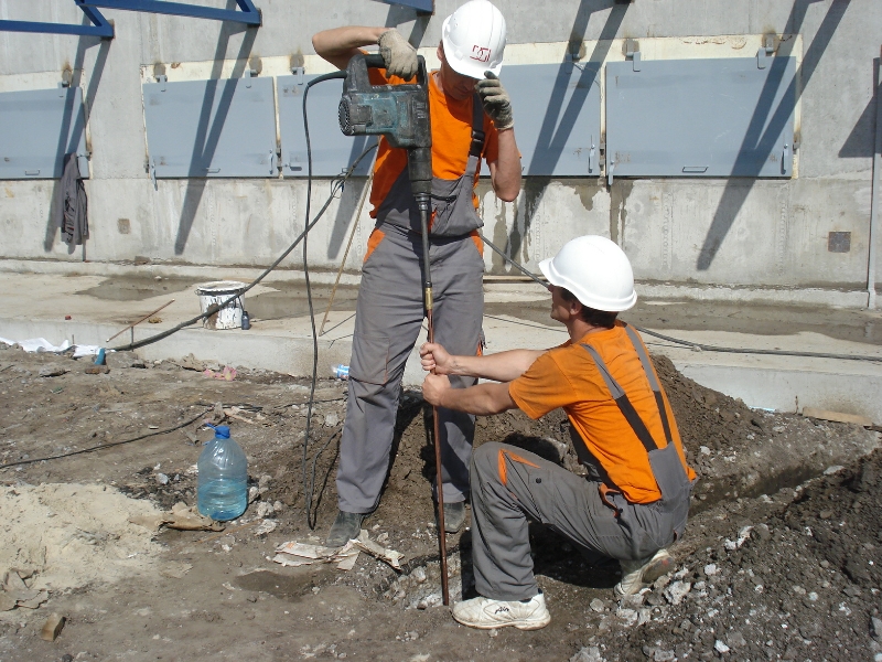
In order to penetrate the rods into the ground to the required depth, you can drive them in with a sledgehammer. If the soil is soft and the length of the rods does not exceed 3 meters, then manual installation will not take much time and effort. For ease of further installation, it is necessary to install vertical rods in the trench so that they rise from the bottom at a height of 10 - 20 cm.
If the ground is quite rocky, you can use a jackhammer with a special attachment to install vertical rods.

The original installation method is used if there is a tractor-excavator of the “Cockerel” type. The hydraulic bucket control drive allows you to exert sufficient force on a vertically placed rod so that the latter completely enters even into rocky soil.
After installing all vertical grounding conductors, they are connected to each other by horizontally located pieces of reinforcement.
The diameter of the horizontally located rods must be at least 10 cm, otherwise the resistance reading at the required level will not be achieved.
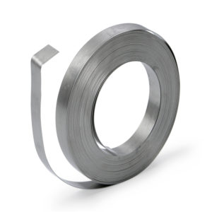
The rods can be connected to each other using steel tape. The width of the tape must be at least 48 mm, and the thickness of the metal must be at least 4 mm. Welding must be performed with high quality so that a corrosion process does not form at the joints of the metal, which can be significantly enhanced by currents passing through the weld.
To ensure the unhindered flow of electric current through the conductor, a resistance of vertical grounding conductors of 4 ohms should be provided along the entire perimeter of the electrical circuit. If it is not possible to achieve this ideal resistance value, a deviation of this value up to 10 ohms is permissible, without compromising the protective properties of vertical grounding.
If immediately after installing the electrical protection it is put into operation, then the places where the vertical rods are located must be watered with a significant amount of water. In this way, it is possible to restore the structure of the soil, which will most effectively transfer electrical potential from the metal rods to the ground.
Self-installation
Vertical grounding electrodes can be installed independently. During installation, it is necessary to know the composition of the soil in order to determine the approximate installation depth of the working electrodes. To install grounding, you will need to purchase a welding machine and required amount electrodes to weld vertical and horizontal grounding conductors.
It is not recommended to use various clamps and other threaded connections to connect metals. Over time, such places can significantly degrade the conductivity of a section of the electrical circuit, which will negatively affect the effectiveness of the ground loop. If the soil does not freeze in winter time to a depth of more than 0.5 meters, and is not rocky or stony, then a round rod no more than 1.5 meters long can be used.
Under unfavorable conditions for installing grounding, the depth of the rods should be at least 3 meters, and the distance between them can be reduced to 4 meters. It is not recommended to further reduce the distance between the electrodes, otherwise the total resistance of the grounding installation may increase significantly due to the shielding effect.
If you don’t want to install the grounding yourself, you can contact specialized companies that will install vertical grounding in the area adjacent to the house in the shortest possible time. Although such services will cost money, the time savings can be significant. And if this resource is very important, then it is better to entrust the work to professionals.
Grounding housings and other parts of industrial and household electrical installations that are not usually energized allows the electric current to be discharged into the ground. This is provided for by the Rules safe operation electrical installations of consumers and applies to the flanges of support insulators, switchboards and control cabinets, handles of disconnector drives, housings of instrument transformers, welding machines and other equipment. Installation of the grounding system involves installing grounding pins and attaching grounding conductors to them, connected to the housings of electrical equipment.
Grounding of the welding machine, which is a stationary installation, is carried out in order to ensure its safe operation. The basic requirements for grounding are as follows:
- All non-current-carrying parts of electric welding installations and one secondary terminal are grounded.
- Welding equipment must be equipped with a special contact (in the form of a bolt or stud) intended for grounding connection.
- The grounding bolt must have a contact pad marked with a special grounding sign.
- Sequential grounding of several installations is prohibited: a separate connection point must be provided for each.
Portable welding automatic installations and semi-automatic machines connected to the network alternating current over 42 V (and over 110 V DC), are also equipped with grounding contacts. In the event that grounding (grounding) cannot be used for installation or installation of grounding is difficult, the electrical equipment must have an RCD (residual current device).
Grounding can also be used for lightning protection.
For objects powered from a step-down transformer with a solidly grounded neutral and a voltage on the secondary winding of 380/220 V, re-grounding is arranged at the input. In this case, the resistance of the grounding loop, according to the PUE, should not be greater than 10 Ohms. In order to ensure such parameters, it is necessary to use grounding conductors with a large contact area and good conductivity. Their surface must be free of oil and paint. Suitable for this:
- metal pipelines (except those associated with flammable liquids and gases);
- metal cable sheaths;
- casing;
- foundation elements.
In this case, the installation diagram of the grounding loop should provide for their double connection to the grounding line. Welding is used to connect grounding conductors to grounding conductors. In this case, the welding seam should be twice as wide as the rectangular shape of the conductor (in cross-section) and six times as wide as the round one. If welding cannot be used, clamps are used, which, like welding seams, are protected from corrosion by a layer of bitumen. Before applying clamps, the surface of the natural grounding conductor in this place must be cleaned.
In hazardous areas, natural grounding can only be used as an additional one. The main one should be artificial grounding, made in accordance with the PUE.
The internal ground loop is attached anchor bolts directly to the wall. Where they intersect with cables or pipelines, protection from pipes is provided. In rooms with high levels of dampness and acidity, the internal grounding loop is mounted on supports at a distance of 100 mm from the walls.
Types of ground electrodes
In the absence of natural grounding conductors, an external grounding loop is installed, to which the corresponding leads and terminals of the electrical equipment are connected.
Artificial grounding can be implemented with vertical or horizontal grounding conductors. For vertical ones, steel pipes or angles are used, which are connected to each other, resulting in the formation of a contour. The connecting elements are horizontal grounding conductors: metal strips with a thickness of at least 4 mm or round reinforcement with a diameter of 10 mm or more are used for this.
Horizontal grounding conductors can be made in the form of metal strips laid at the bottom of pits prepared for the construction of a foundation. The strips are arranged so that their largest surface is oriented towards the ground. The cross-section of the strips is 30×4 mm; round steel reinforcement with a diameter of 12 mm can be used.
It is not allowed to use aluminum to create buried grounding, since this metal quickly breaks down in the soil due to electrocorrosion.
Where installation of horizontal grounding is impossible (for example, due to the lack of land free from asphalt and other communications), deep grounding technology is used. At the same time, at one point in the ground different ways metal rods are introduced: the end of each next one is connected to the previous one, forming a ground electrode with a large contact area.
How is horizontal grounding performed?
The grounding installation technology is simple. A grinder with a metal circle, welding, a sledgehammer and a metal brush for cleaning welding areas are used to perform the work. The whole process consists of the following points.

- We prepare necessary materials. You will need:
- a strip of the same material 40×4 mm or round wire (reinforcement) with a diameter of 10 mm;
- hot-dip galvanized corners 2.5 m each (section 50×50×5 mm – 3-4 pcs).
- We are drawing up a project in which sufficient space is provided in the adjacent territory for the location of vertical electrodes at a distance exceeding their own length (that is, more than 2.5 m).
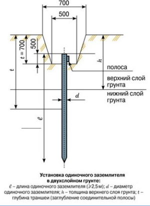
- A trench is dug about 400 mm wide and 700-800 mm deep.
- In the designated places, the corners with sharpened tops are hammered in with a sledgehammer, leaving 200 mm on the surface.
- The ground loop is welded: a strip of metal is welded to the tops protruding above the ground.
- The grounding is welded with a wire or bus laid to the distribution board or control cabinet.
- Welding the ground strip with corners and the connecting wire is coated with bitumen mastic to protect against corrosion.
- All elements are sprinkled with earth, which is then compacted.
- Ground resistance is measured.
- If the result obtained exceeds 4 Ohms, it is necessary to add another vertical element, which is connected by welding to the rest of the structure.

Installation of vertical deep grounding
In addition to saving space, deep grounding has another advantage: due to contact with the lower, dense and saturated groundwater layers of soil, good conductivity is achieved.
Do-it-yourself grounding installation is carried out in various ways. The choice depends on the properties of the soil in the area:
- for loose rocks, pressing, screwing and driving in electrodes consisting of individual rods is used;
- Electrodes are immersed in dense and frozen soils by driving or vibration immersion;
- in rock formations, the electrodes go deep into a specially drilled hole.
Depending on the soil, different electrodes are used. They come in square, corner and round. Their cross-section is selected for soft soils in the range of 12 - 14 mm (if the driving depth is sufficient up to 6 m), for dense soils and significant driving depth (over 10 m) the cross-section of the electrodes should be 16 - 20 mm. For deep driving, special vibrators are used; in other cases, using a jackhammer or a powerful hammer drill is sufficient.
If nothing is known about the properties of the soil, when installing deep grounding proceed as follows.

- Electrodes of the required length are prepared.
- The first section of the grounding conductor is hammered in and the grounding resistance is measured.
- The next element is welded to the upper end of the hammered section and hammered in.
- Measurements are carried out again and continue until the required value of grounding resistance is obtained.
- A bar or wire is welded to the upper end of the recessed electrode, the other end of which is inserted into a distribution cabinet or panel.