Today I will briefly consider the question of what drivers are installed in LED lamps. Types, types, their characteristics. I should immediately note that all LED lamp drivers can be divided into two types: electronic and capacitor-based. We will talk about some of the advantages and disadvantages today. But by and large, I will reveal this issue in more detail not much later and add it to this article. Thus, I assume that “LED drivers for lamps” will become quite voluminous. Moreover, a lot of material has accumulated.
They produce drivers designed for one or a group of LEDs. Designed for a specific current.
Electronic drivers for LED lamps
 Driver for LED lamp
 In general, for good reason, any electronic driver must have a key transistor in order to relieve the driver control chip. To eliminate or smooth out ripple as much as possible, there should be a capacitor at the output. The cost of drivers of this type is not small, unlike ballast ones, but they stabilize currents up to 750 mA and higher, which ordinary “spineless” ones cannot do. Can. But it’s better not to use more than 200 mA... Again, operating experience.
Ripple is not the only drawback of drivers. Another can be considered high-frequency interference. If your socket is connected to a lamp (apartment wiring), then problems with reception of digital television, IP, etc. cannot be avoided. Naturally, it will be difficult to catch the radio. Now I’m wondering: “Will Wi-Fi suffer?”... We need to run experiments...
In good drivers, electrolytes should be installed to smooth out pulsations, and ceramics will be used to reduce RF interference. Ideally, the driver contains both condensers. But such a combination is very rare. Especially in Chinese lamps. There are some "individuals", but they are very few. Someday I'll talk about them.
Well, one more general information. For those who love “crazy hands”. You can always change the output current of your electronic driver by playing around with the resistor values. Although, is it necessary? A huge number of drivers are already available and choosing the right one is not a problem. And you don't have to buy an expensive one. The Chinese have long learned to produce quite decent electronics.
Let's move on to the equally common so-called drivers - on capacitors. I always call them “so-called”. Why? This will be clear from the conclusions at the end of the article.
LED drivers for capacitor-based lamps
Let us turn to any standard LED lamp circuit that uses such “drivers”

The scheme is general and in some cases it is constantly modified. Chinese manufacturers especially love to throw things out of there.
Often in cheap lamps we can “observe” a pulsation of 100 percent. In this case, you don’t even have to look inside the lamp to confirm that one of the capacitors is missing. Namely the second one. Because the first is necessary to regulate the output current. They certainly won’t take him anywhere))).
For those who want to assemble such drivers themselves, there are formulas that can be found on the Internet. And from them calculate the capacitor rating.
This can be considered a big advantage of this type of driver. After all, the lamp power can be adjusted by simply selecting a capacitor. The downside is the lack of electrical safety. It is prohibited to touch the switched-on lamp with your hands. Electrical injury is guaranteed.
Another advantage is the 100 percent efficiency, because the losses will only be on the LEDs themselves and the resistances.
A huge minus is pulsation. It is taken as a result of rectification of the mains voltage and is about 100 Hz. According to GOST and SANPIN, pulsation is permissible from 10-20 percent, and then depending on the room in which the light source is installed. You can reduce the ripple by selecting the value of capacitor No. 2. But all the same, you will not get a complete absence, but only slightly smooth out the splashes.
This is the second and main disadvantage of this type of driver. As they say: what is cheap is not always useful. And pulsation is very harmful to a healthy body. Yes, and for those who are not healthy))).
Comparison of electronic and ballast drivers for LED lamps
From all of the above (perhaps confusingly) we can make a comparative description between two types of drivers for LED lamps:
| Drivers | Ballast on capacitors | Electronic |
| Possibility of electrical injury | High. Due to the lack of galvanic isolation from the network. It is prohibited to touch the elements with your hands when the lamp is on | Low |
| High currents | It is not possible to obtain high currents for the diodes to glow, as a result of the need for large capacitors. Structurally, the lamp will be large in size. In addition, larger capacitors lead to increased inrush currents, which leads to rapid failure of switches | Can be obtained without any problems |
| Ripple | Big. About 100 Hz. It is almost impossible to get rid of due to the need to introduce large capacitance capacitors at the output that filter out ripple | Easily adjustable or missing |
| Scheme | The scheme is very simple. Easy to assemble on the knee and does not require extensive knowledge of radio electronics | The scheme is complex. With a lot of electronic components |
| Output voltage | Easy to adjust | Output voltage range is narrow |
| Price | Low | High |
| Current adjustment | By changing the capacitance of the input capacitor | More complex. As a rule, only with the help of resistors. And that's not always the case. It all depends on the complexity of the assembled circuit |
Which LED drivers for lamps are better and which are worse is up to you to decide. Both have both strengths and weaknesses. Both of them can be used. Only in different rooms. But for myself, I introduced a simple gradation. I never consider those lamps that are assembled on ballasts from capacitors to be high-quality lamps due to pulsation. I am a supporter of a healthy lifestyle))) and therefore I throw such light sources straight into the trash.
Video material on the topic of LED drivers for lamps
And finally, as usual, I offer an interesting video about LED drivers. Or rather, about one, the simplest one, which you can assemble on your knee yourself.
Powerful LEDs in lighting devices are connected through electronic drivers that stabilize the current at their output.
Nowadays, so-called energy-saving fluorescent lamps (compact fluorescent lamps - CFLs) have become widespread. But over time, they fail. One of the causes of the malfunction is burnout of the lamp filament. Do not rush to dispose of such lamps because the electronic board contains many components that can be used in the future in other home-made devices. These are chokes, transistors, diodes, capacitors. Typically, these lamps have a functional electronic board, which makes it possible to use them as a power supply or driver for an LED. As a result, in this way we will get a free driver for connecting LEDs, which is even more interesting.
You can watch the process of making homemade products in the video:
List of tools and materials
-energy saving fluorescent lamp;
-screwdriver;
- soldering iron;
-tester;
-white LED 10W;
-enamel wire with a diameter of 0.4 mm;
-thermal paste;
- diodes of the HER, FR, UF brand for 1-2A
-desk lamp.
Step one. Disassembling the lamp.
We disassemble the energy-saving fluorescent lamp by carefully prying it off with a screwdriver. The lamp bulb cannot be broken as there is mercury vapor inside. We call the filament of the bulb with a tester. If at least one thread shows a break, then the bulb is faulty. If there is a working similar lamp, then you can connect the bulb from it to the electronic board being converted to make sure that it is working properly.

Step two. Remaking the electronic converter.
For the modification, I used a 20W lamp, the choke of which can withstand a load of up to 20 W. For a 10W LED this is enough. If you need to connect a more powerful load, you can use an electronic lamp converter board with the appropriate power, or change the inductor with a larger core.
It is also possible to power LEDs of lower power by selecting the required voltage by the number of turns on the inductor.
I mounted wire jumpers on the pins to connect the lamp filaments.


20 turns of enamel wire need to be wound over the primary winding of the inductor. Then we solder the secondary wound winding to the rectifier diode bridge. We connect 220V voltage to the lamp and measure the voltage at the output from the rectifier. It was 9.7V. An LED connected through an ammeter consumes a current of 0.83A. This LED has a rated current of 900mA, but in order to increase its service life, the current consumption is specially reduced. The diode bridge can be assembled on the board by surface mounting.
Diagram of the converted electronic converter board. As a result, from the inductor we get a transformer with a connected rectifier. Added components are shown in green.

Step three. Assembling an LED table lamp.
We remove the 220 volt lamp socket. I installed a 10W LED using thermal paste on a metal lampshade of an old table lamp. The table lamp shade serves as a heat sink for the LED.

The electronic power board and diode bridge were placed in the housing of the table lamp stand.
To design LED lamps, power sources—drivers—are constantly required. With a large volume, it is quite possible to assemble the drivers yourself, but the cost of such drivers is not so low, and manufacturing and soldering double-sided printed circuit boards with SMD components is a rather labor-intensive process at home.
I decided to make do with a ready-made driver. What was needed was an inexpensive driver without a housing, preferably with the ability to adjust the current and dimming.
I redrawn the diagram and modified it a little


Characteristics without capacitors ~0.9V and 8.7% (light flux ripple)
The output capacitor is expected to reduce ripple by half ~0.4V and 4%
But a 10uF capacitor at the input reduces ripple by 9 times ~0.1V and 1%, although adding this capacitor significantly reduces PF (power factor)
Both capacitors bring the output ripple characteristics closer to the specifications ~ 0.05V and 0.6%

So, ripple was defeated with the help of two capacitors from the old power supply.
Improvement No. 2. Setting the driver output current
The main purpose of the drivers is to maintain a stable current to the LEDs. This driver consistently produces 600mA.
Sometimes you want to change the driver current. This is usually done by selecting a resistor or capacitor in the feedback circuit. How are these drivers doing? And why are three parallel low-resistance resistors R4, R5, R6 installed here? 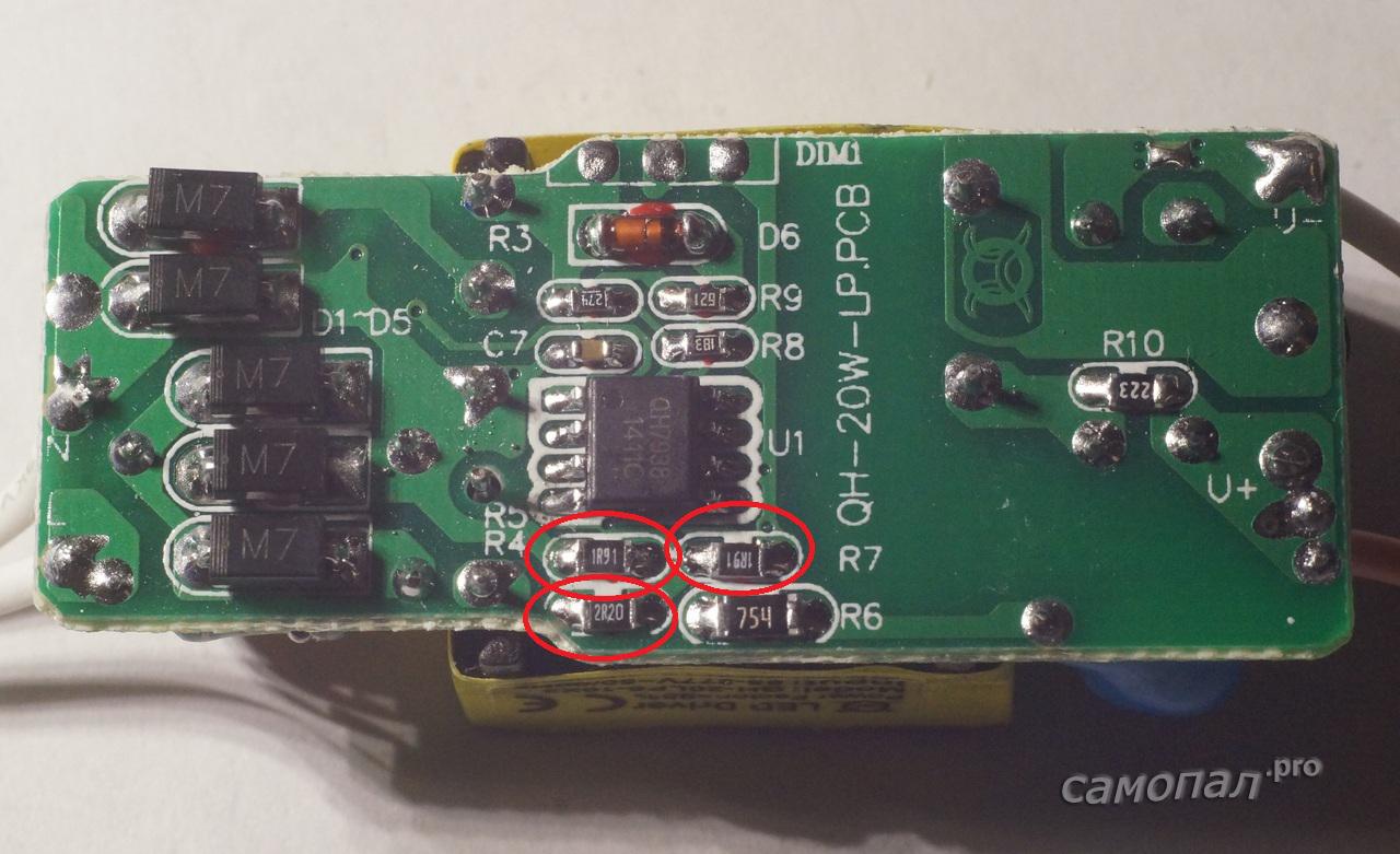
Everything is correct. They can set the output current. Apparently, all drivers are of the same power, but for different currents and differ precisely in these resistors and the output transformer, which gives different voltages.
If we carefully remove the 1.9 Ohm resistor, we get an output current of 430 mA by removing both 300 mA resistors.

You can go the opposite way by soldering another resistor in parallel, but this driver produces a voltage of up to 35V and with a higher current we will get excess power, which can lead to driver failure. But 700mA is quite possible to squeeze out.
So, by selecting resistors R4, R5 and R6, you can reduce the driver output current (or increase it very slightly) without changing the number of LEDs in the chain.
Revision 3. Dimming
There are three pins on the driver board labeled DIMM, which suggests that this driver can control the power of the LEDs. The datasheet for the microcircuit speaks about the same thing, although it does not contain typical dimming circuits. From the datasheet you can glean information that by applying a voltage of -0.3 - 6V to leg 7 of the microcircuit, you can obtain smooth power control.
Connecting a variable resistor to the DIMM pins does not lead to anything, in addition, leg 7 of the driver chip is not connected to anything at all. So again improvements.
Solder a 100K resistor to leg 7 of the microcircuit

Now by applying a voltage of 0-5V between ground and resistor we get a current of 60-600mA

To reduce the minimum dimming current, you must also reduce the resistor. Unfortunately, nothing is written about this in the datasheet, so you will have to select all the components experimentally. I was personally satisfied with dimming from 60 to 600mA.
If you need to organize dimming without external power, you can take the driver supply voltage ~15V (leg 2 of the microcircuit or resistor R7) and apply it according to the following circuit. 
Well, finally, I feed PWM from D3 of the Arduino to the dimming input.

I’m writing a simple sketch that changes the PWM level from 0 to maximum and back:
#include
void setup() (
pinMode(3, OUTPUT);
Serial.begin(9600);
analogWrite(3,0);
}void loop() (
for(int i=0; i< 255; i+=10){
analogWrite(3,i);
delay(500);
}
for(int i=255; i>=0; i-=10)(
analogWrite(3,i);
delay(500);
}
}
I get dimming using PWM.
PWM dimming increases output ripple by about 10-20% compared to DC control. The maximum ripple increases approximately twice when the driver current is set to half the maximum.
Checking the driver for short circuit
The current driver must respond correctly to a short circuit. But it’s better to check the Chinese. I don't like such things. Stick something under voltage. But art requires sacrifice. We short-circuit the driver output during operation:
The driver tolerates short circuits normally and restores its operation. There is short circuit protection.
Let's sum it up
Pros of the driver
- Small dimensions
- Low cost
- Possibility of current adjustment
- Dimmable
Minuses
- High output ripple (eliminates by adding capacitors)
- The dimming input needs to be soldered
- Little normal documentation. Incomplete datasheet
- During operation, another disadvantage was discovered - interference on the radio in the FM range. It can be treated by installing the driver in an aluminum case or a case covered with foil or aluminum tape.
The drivers are quite suitable for those who are comfortable with a soldering iron or for those who are not, but are willing to tolerate output ripples of 3-4%.
useful links
From the series - cats are liquid. Timofey - 5-6 liters)))

Each diode, in turn, has a voltage drop at different currents indicated in its description. For example, for a red 660 nm diode at a current of 600 mA it will be 2.5 V:
.jpg)
The number of diodes that can be connected to the driver, the total voltage drop must be within the limits of the driver's output voltage. That is, a 50W 600 mA driver with an output voltage of 60-83 V can connect from 24 to 33 red 660 nm diodes. (That is, 2.5*24 = 60, 2.5*33 = 82.5).
Another example:
We want to assemble a red + blue bicolor lamp. We have chosen a red to blue ratio of 3:1 and want to calculate which driver we need to take for 42 red and 14 blue diodes. We calculate: 42 * 2.5 + 14 * 3.5 = 154 V. This means that we will need two drivers 50 W 600 mA, each will have 21 red and 7 blue diodes, the total voltage drop on each will be 77 V, which gets into its output voltage.
Now some important clarifications:
1) You should not look for a driver with a power of more than 50 W: they are available, but they are less efficient than a similar set of drivers with a lower power. Moreover, they will get very hot, which will require you to spend additional money on more powerful cooling. In addition, drivers with a power of more than 50W are usually much more expensive, for example, a 100W driver can be more expensive than 2 50W drivers. Therefore, there is no point in chasing them. And it’s more reliable when the LED circuits are divided into sections; if something suddenly burns out, not everything will burn out, but only part of it. Therefore, it is beneficial to divide it into several drivers, rather than trying to hang everything on one. Conclusion: 50W is the best option, no more.
2) Drivers have different currents: 300 mA, 600 mA, 750 mA - these are the common ones. There are quite a lot of other options.
By and large, it will be more efficient in terms of efficiency per 1 W to use a 300 mA driver; it will also not load the LEDs much, and they will heat up less and last longer. But the main disadvantage of such drivers is that the diodes will work at half capacity, and therefore they will be required approximately twice as much as for an analogue with 600 mA.
A 750mA driver will drive the diodes to the limit, so the diodes will get very hot and will need very powerful, well designed cooling. But even despite this, they in any case degrade from overheating earlier than the average “life” of LED lamps operating, for example, at 500-600 mA current.
Therefore, we recommend using drivers with a current of 600 mA. They turn out to be the most optimal solution in terms of the price-efficiency-service life ratio.
3) The power of the diodes is indicated as nominal, that is, the maximum possible. But they are never powered to the maximum (why - see point 2). It is very simple to calculate the real power of the diode: you need to multiply the current of the driver used by the voltage drop of the diode. For example, when connecting a 600 mA driver to a 660 nm red diode, we get the actual voltage on the diode: 0.6(A) * 2.5(V) = 1.5 W.
I bought 10 W 900 lm warm white LEDs on AliExpress to try. The price in November 2015 was 23 rubles per piece. The order arrived in a standard bag, I checked everything was in good condition. 
To power LEDs in lighting devices, special units are used - electronic drivers, which are converters that stabilize the current rather than the voltage at their output. But since the drivers for them (I also ordered on AliExpreess) were still on the way, I decided to power them from ballast from energy-saving lamps. I've had several of these faulty lamps. whose filament in the bulb burned out. As a rule, the voltage converter for such lamps is working properly, and it can be used as a switching power supply or LED driver.
We disassemble the fluorescent lamp. 
For the conversion, I took a 20 W lamp, the choke of which can easily deliver 20 W to the load. For a 10W LED, no further modifications are required. If you plan to power a more powerful LED, you need to take a converter from a more powerful lamp, or install a choke with a larger core.
Installed jumpers in the lamp ignition circuit. 
I wound 18 turns of enamel wire around the inductor, solder the terminals of the wound winding to the diode bridge, apply mains voltage to the lamp and measure the output voltage. In my case, the unit produced 9.7V. I connected the LED through an ammeter, which showed a current passing through the LED of 0.83A. My LED has an operating current of 900mA, but I reduced the current to increase the resource. I assembled the diode bridge on the board using a hinged method.
Remodeling scheme. 
I installed the LED using thermal paste on a metal lampshade of an old table lamp. 
I installed the power board and diode bridge into the body of a table lamp. 
When working for about an hour, the LED temperature is 40 degrees. 
To the eye, the illumination is like that of a 100-watt incandescent lamp. 